


Technical Segment
Using the Icom AH-4 with the IC-705
In this article, FB NEWS Worldwide editors are going to introduce how to use the Icom AH-4 Automatic Antenna Tuner with the IC-705. It is reported that an Icom antenna tuner especially for the IC-705 is being planned for release, but we just wanted to use a wire antenna with the IC-705 “right now.”
Please note that this is not an officially recommended method by Icom.
Pin assignments of the IC-705 TUNER jack
There is a TUNER jack on the right side of the IC-705, and according to the Icom webpage, an antenna tuner will be released in the future that can be connected to it.
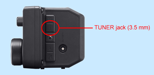
Right side of the IC-705
This is a three-conductor stereo jack, and [KEY], [START], and [GND] are assigned sequentially from the tip.

Pin assignment
Connecting the AH-4 to the IC-705
Unlike the IC-7610 or IC-7300, there is no jack especially for the AH-4 on the IC-705. However, we assumed that if we connect the control lines of the AH-4 to the IC-705’s TUNER jack, and separately supply the 13.8 V DC power...the antenna tuner might work well.

When the AH-4 is connected to the IC-7300, the 13.8 V power is supplied from the radio to the AH-4.

When the AH-4 is connected to the IC-705, both the AH-4 and IC-705 must be connected to the same power supply and grounded at the same internal GND terminal.
To connect the AH-4 to the IC-705, connect the three control lines for KEY, START and GND to the tip, ring, and sleeve of a 3.5 mm stereo plug. Connect the fourth power line to a suitable power connector, which is required to supply 13.8 V DC power to the tuner. You can purchase a 3.5 mm stereo plug at a parts shop, but we also recommend trying out a screw-type connector.

Direct wiring with a screw-type connector is convenient for a trial.
Now, there are two ways to connect the AH-4 to the IC-705.
1. Build a control cable for the AH-4.
2. Build a conversion cable that is connected to the AH-4 supplied cable.
When you chose No.1:
Purchase a 4-conductor shielded cable and build the control cable. One side is for the J2 connector in the AH-4, the other side is for the IC-705 TUNER jack and the DC power supply.

The 4-conductor shielded cable we bought.
When you chose No.2:
To make a conversion cable, buy the necessary spare parts described below. Contact your local distributor for ordering details. Because the AH-4 standard supplied cable is too long for the IC-705, you can cut and shorten it if needed, but we are not responsible for any trouble that may occur.
Required spare parts:
Component name: 1490R1
Icom component number: 6510001940
Component name: 1189TL
Icom component number: 6510007460

Completed conversion cable
Verifying operation
This is a screen capture before we connect the AH-4 to the IC-705. [TUNER] is grayed out.

The IC-705 FUNCTION screen before connecting
Connect both the AH-4 and the IC-705 to the same regulated power supply after turning it OFF. Then turn ON the power supply to power ON the AH-4 first, then push the [POWER] key in the IC-705 to turn ON the IC-705. This sequence is important for the AH-4 to be recognized by the IC-705. Now look at the IC-705 FUNCTION screen again to confirm that [TUNER] is no longer grayed out. Touch and hold [TUNER] for one second to turn it ON.

The IC-705 FUNCTION screen after connected
When tuning is started, the [TUNE] icon blinks red in the upper-left corner of the IC-705 screen. When tuning is complete, the icon stops blinking and is lit white.

The IC-705 screen after tuning
We look forward to seeing the Icom antenna tuner!
Now we figured out that we can use the AH-4 connected to the IC-705...but we can’t wait for the official Icom antenna tuner, to bring out the best in the IC-705!