
Technical article
Let's operate FT8 with the newly announced IC-7610
FT8, one of the data communication protocols, is getting very popular, especially with the recent low sunspot conditions. We can hear its signal tone in the HF bands every day. FT8 was originally designed for communications under extreme weak signal conditions. The FB NEWS staff recently operated the FT8 mode, and in this issue we would like to introduce you to the connections, settings, and operations using the newly announced IC-7610.
Recently, most transceivers have a useful USB port to process sound data. You can simply connect a USB cable between your transceiver and your PC and operate in the popular digital modes. You do not need to use a troublesome external interface unit.
We recommend that you take the opportunity to try out the popular FT8 mode, if you have not already started.
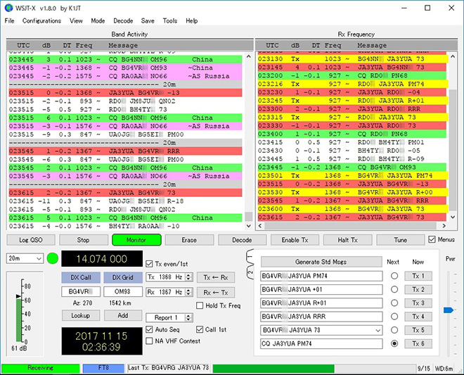
FT8 operation example screen
Initial preparation
Before connecting the IC-7610 and a PC, it is necessary to first install a USB driver on the PC.
Download the latest version of the USB driver that corresponds to the IC-7610 from the Icom website, and install it on your PC.
Next, download the WJST-X*1 application software from the K1JT website and install it on your PC, to use FT8.
http://physics.princeton.edu/pulsar/k1jt/wsjtx.html
*1 WSJT-X is only the software you can operate in the FT8 mode as of the middle of December, 2017. In our tests, we used software version v1.8.0.
Connections
Connect the USB cable between the IC-7610 USB-1 port, as shown below, and your PC. We recommend a USB cable with a ferrite bead attached, to prevent RF feedback.
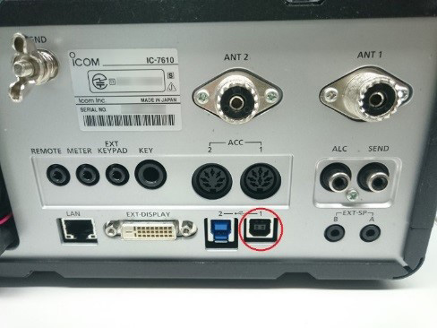
○:USB-1 port
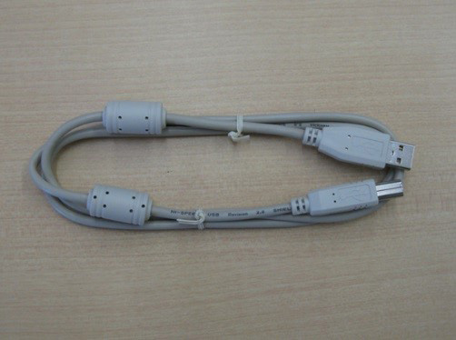
A type A/B USB cable
First of all, make sure that both the IC-7610 and the PC are turned OFF. Then, turn ON the PC power. After Windows has completely booted up, turn ON the IC-7610’s power. The PC recognizes the connected IC-7610. Open the devise manager to make sure that two COM ports are displayed, and write down the COM port numbers for later application settings. These are all the cable and PC connections and setting preparations that are needed.

COM 4 and COM 5 are usable in this example
Settings in the IC-7610
To connect the IC-7610 USB port and the PC using one USB cable for modulation and demodulation, you need to have the USB settings enabled.
To set the USB settings on the IC-7610, first make sure that the DATA2 MOD is set to USB, as described below.
Push [MENU], then touch [SET] à [Connectors] à [MOD Input] to display the DATA MOD settings. Touch DATA2 MOD, then touch USB, if it is not already selected. Then, push [MENU] to return to the normal operating screen.
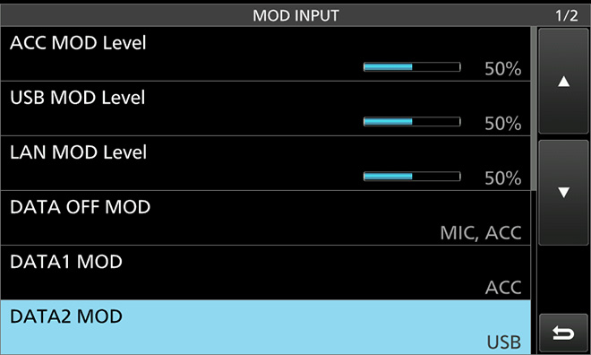
Set mode screen
Next, the settings for CI-V
Push [MENU], then touch [SET] à [Connectors] à [CI-V] à [CI-V Baud Rate] to display the CI-V Baud Rate setting. Touch [19200].
Next, touch CI-V address, and then touch [+] or [-], or rotate [MULTI], to set the address to 8Eh*2, and push [EXIT].
Next, touch CI-V USB Port, the touch “Link to [REMOTE]”.
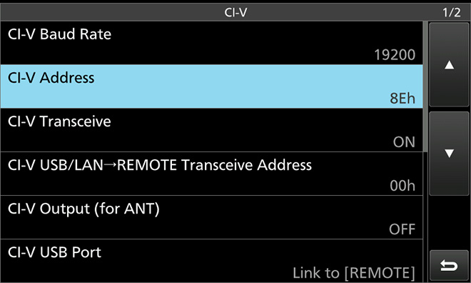
CI-V Settings screen
*2: 8Eh is the IC-785x’s default CI-V address. WSJT-X does not yet list the IC-7610 in the software as of December 2017. Therefore, you need to use the current settings for the IC-7850/7851 as the IC-7610 address. When the WSJT-X is updated to include the IC-7610, just skip this change and keep the same 98h address as that is the default CI-V address of the IC-7610.
Those are all the IC-7610 settings that are needed.
Settings in the WSJT-X software
Start the WSJT-X software, then click “File”à”Settings” to select the “General” tab menu. Input all necessary information on the screen, such as your call sign, your grid location, and so on.
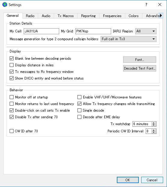
General Tab setting screen
You can refer to the example settings as shown in the screen capture above. However, the call sign and grid location must be your own.
Next, select the “Radio” tab and input all necessary information, as described in the instructions below.
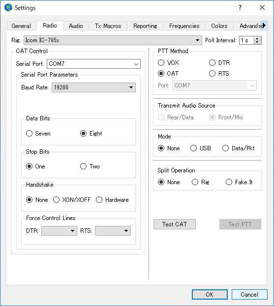
Radio Tab setting screen
1. Rig: Icom IC-785x (until the software is updated to display the IC-7610)
2. Serial Port: Two COM ports should be displayed on two lines if you connect the IC-7610. Select the COM port number displayed on the top line that is displayed in the pull-down menu. (In the example above, COM7 is selected.)
3. Baud Rate: 19200
4. Others: Select each setting as shown in the above example.
When you set all items described above, click the [Test CAT] button in the bottom right corner of the screen. If all items are properly set, the color of the button changes to green. If the color changes to red, double check all settings, especially the COM Port number. However, if you still have a problem, select the other COM Port number, or confirm the CI-V address is correct in both the software and the IC-7610.
Next, click [Test PTT] on the right bottom corner while the [Test CAT] is green. [Test PTT] should change to red. Even if the IC-7610 “TX/RX” indicator lights red on the front panel, (indicating “transmit”) it is not a problem at the moment because no modulation is applied to the IC-7610, and no transmit power is output. Then, click [Test PTT], to return to the normal configuration status.
Click the Audio tab on the Setting screen to set the items described below.
1. Input: Select the "USB Audio CODEC" as the microphone input.
2. Output, Select the "USB Audio CODEC" as the speaker output.
Those are all basic settings, and you can now operate in the FT8 mode. Click the [OK] button to close the Setting screen, and then the main WSJT-X screen is displayed.
Basic operations for FT8
1.Turn OFF both the IC-7610 and the PC. Then, turn ON the IC-7610 first and next turn ON the PC.
Note: If the turn ON is reversed, it may cause an error in the WSJT-X.
After the WSJT-X application software starts up, make sure that the PC time is accurate within +/- 1 second. If the time is not correct, set the time in the Windows time setting.
Click “Mode” on the top menu line and select “FT8.”
2.Select an operating band. There is the pull-down band selection window located slightly below the center on the left side on the main screen. Click the “v” (down arrow) to select the desired operating band. If you select the “20m” band, for example, the transceiver frequency is automatically changed to 14.074.000 MHz by a CI-V command.
3.Set the transceiver mode to USB-D2. First, touch the [SSB] mode button on the IC-7610 to open the Mode screen. Then, touch the [DATA] button to select “USB-D2.”
If “USB-D2” is not displayed, touch and hold the [DATA] button several times to select USB-D2, then touch [EXIT] to close the mode screen.
Push [FILTER] several times to set BW filter bandwidth to 3.0 kHz, as shown in the screen example.
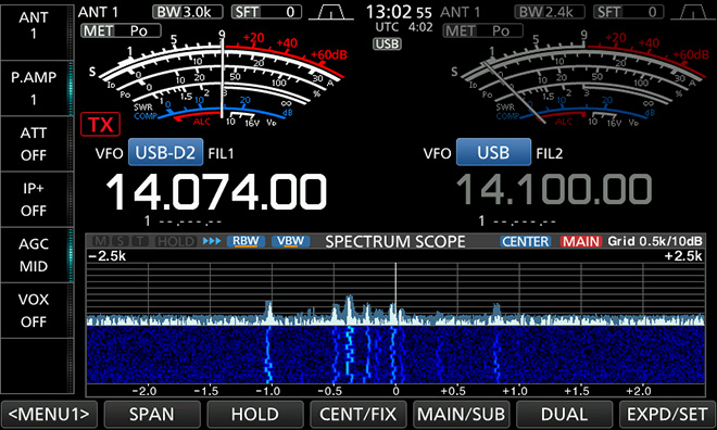
Example setting: Operating mode is set as USB-D2 and BW is set to 3 kHz.
(The Waterfall screen shows that FT8 signals are being received)
4.When the band is open, the IC-7610 receives FT8 signals and the PC starts decoding those signals. The PC screen shows the decoded results. The screen refreshes every 15 seconds. When a station is calling CQ, the station data is displayed in pink.
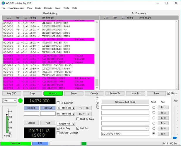
[WSJT-X Main screen example]
5.Observe QSOs by other stations to learn how QSOs are made.
6.Double-click on a station colored in pink with the mouse. The [Enable Tx] button changes to red, and the transceiver automatically starts transmitting to call the station. Quickly slide the “Pwr” slide control on the right bottom hand corner to adjust the transceiver output power. You can check the transmit power on the IC-7610 PO meter. The output power should be as low as possible, but still enough make a QSO.
7.When you receive a reply from the station you called, the QSO TX and RX are alternatively changed every 15 seconds in the WSJT-X software. When a part of your message does not properly reach the station, only that part of the message is resent. When the QSO is finished, transmitting automatically stops.
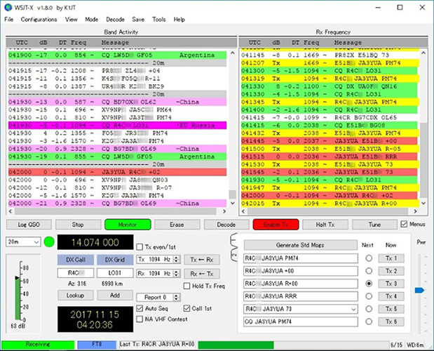
[Activity screen example]
8.If there is no reply from the station, and it sends CQ again, your [Tx1] message is automatically sent again. However, after retransmitting several times and you still have no reply, the transmit signal may not have reached to the station somehow with the current propagation. In that case, click [Enable Tx] to cancel transmitting.
9.If your QSO with a station is successful, click the [Log QSO] button to save the QSO data into the WJST-X software log.
10.Many stations are on the air and it is busy a lot of the time in the FT8 mode, especially on the 20 meter band. If you have not started to operate FT8 yet, install the software, set up your radio and PC and join in the fun.
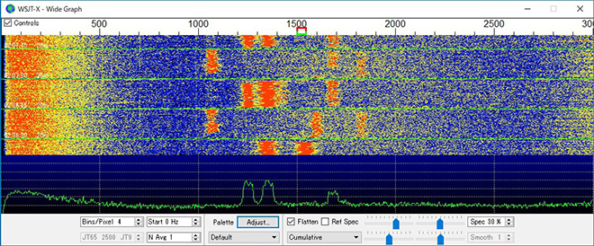
[WSJT-X Waterfall screen example]