


Topics from Around the World
A small dual-band directional antenna for 2m and 70cm
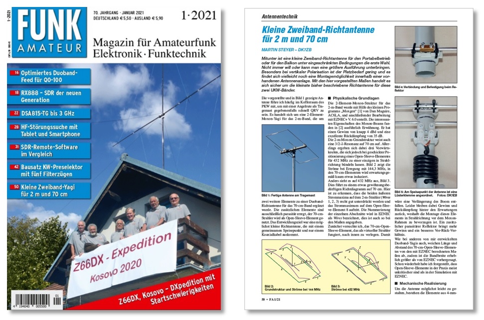
Many amateur radio magazines are sent to the editorial department of FB Magazine from various countries every month. Germany's FUNK AMATEUR is one of the most eye-catching of the magazines. First off, we are impressed that all pages are printed in color. Illustrations and photographs are also used abundantly, and it is very easy to read. The articles are in German, of course, but just by looking at the pictures, we amateur radio operators can roughly understand what is written. Icom has released the IC-705 compact portable transceiver, and compact antennas are popular. This time, the editorial department will briefly translate this antenna article and present it here.
A small dual-band directional antenna for 2m and 70cm
Martin Steyer – DK7ZB
A compact, dual-band, directional antenna is sometimes the first choice for portable operation, or for operating on a balcony under limited conditions. You do not always want to, or simply cannot accommodate a larger antenna. Especially with vertical polarisation, the space requirement is small, and there may still be a mounting option within an existing antenna system. With the dimensions presented here, this is certainly the smallest directional antenna described so far for these two FM bands.
I often carry the antenna describer here, and shown in Figure 1, in the trunk of my car so I can quickly operate, if necessary, with a fishing rod as a mounting mast. It is a 2-element Moxon Yagi for the 2m band, to which two additional elements have been added to form a dual-band directional antenna for the 70cm band. The additional elements are exclusively parasitically excited; the 70cm radiator is used as an Open-Sleeve-Element. The development goal was a directional antenna that was as small as possible, use a common feed point, and only one coaxial cable.
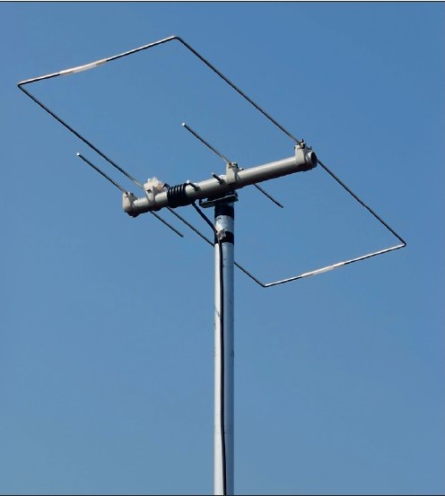
Figure 1. Finished antenna on the mounting mast
Physical principles
The 2-element Moxon design for the 2m band was created using the free program "Moxgen" [1] by Dan Maguire, AC6LA, and subsequent processing with EZNEC+ V.6.0. The interesting properties of the Moxon beam were mentioned in detail in [2]. It has a gain of just under 4 dBd and an excellent front-to-back ratio of 35 dB.
The basic 2m Moxon structure also has a 3/2 λ resonance at 70cm. However, this results in three forward lobes, which can be bundled into one in the beam direction if an Open-Sleeve-Element for 432 MHz is cleverly positioned. Figure 2 shows the currents with excitation at 144.3 MHz; as expected, hardly anything is induced into the 70cm elements.
The situation is different at 432 MHz, shown in Figure 3, which leads to a directional diagram at 70cm that takes some time getting used to it. Here it can be seen that the outer current maxima on the 2m radiators (‘Wires’ 1, 2, and 3) is suppressed quite well, and the current maxima distribution occurs on the Open-Sleeve-Element 8. The numbering of the individual elements is referred to as Wires in EZNEC. This is also stated so in the dimensions.
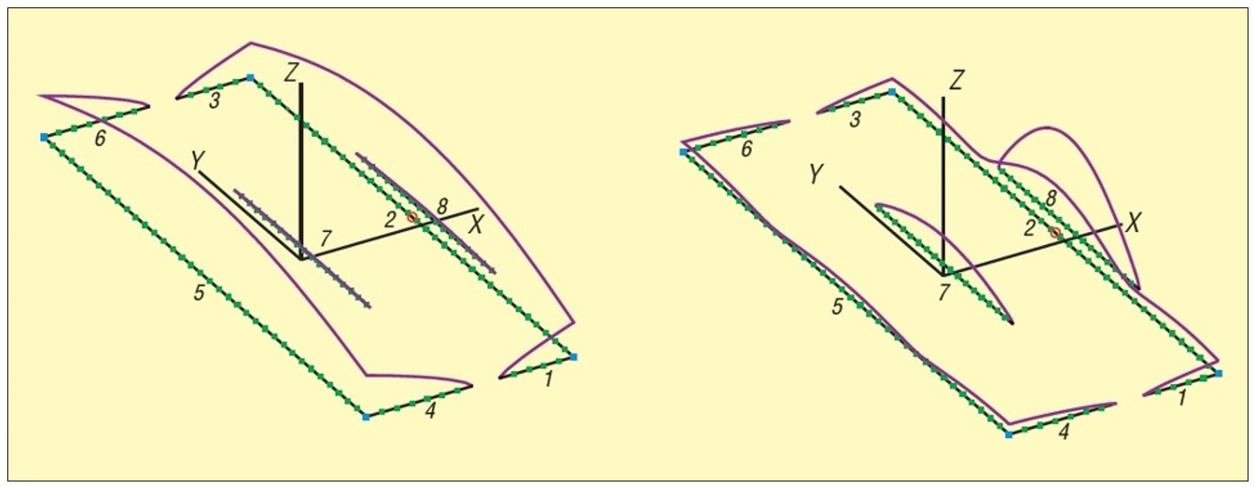
Figure 2. Basic structure and currents at 144 MHz Figure 3. Currents at 432 MHz
First, I tried to move the 70cm Open-Sleeve-Element, which acts as a virtual radiator, inwards. This would have eliminated the need to extend the boom. Unfortunately, this leaves gain and return attenuation below expectations, so mounting this element in the beam direction in front of the Moxon frame is preferable. An additional parasitic reflector brings more gain and a better front-to-back ratio.
As with other dual band Yagis developed by me, the length and distance of the 70cm Open-Sleeve-Element differ from the dimensions calculated with EZNEC, and the bandwidth is considerably wider than predicted by EZNEC. I have repeatedly found that Open-Sleeve-Elements are usually less critical in practice than in simulations with EZNEC.
Mechanical implementation
The antenna should be made as light as possible. The elements are made of 4 mm aluminium rods. I found that aluminium alloy welding rods made of the alloy AlMg3(5754) have proven to be the best. These are very stable and can still be bent at right angles very well. Other alloys can be too soft or even so brittle that they may break when bent in a vice. The 2m rods made of 4 mm solid aluminium offered in DIY stores are also good to use. However, they are often anodised, which has no electrical conductance. Therefore, the anodising must be sanded off at the contact points because it is not conductive.
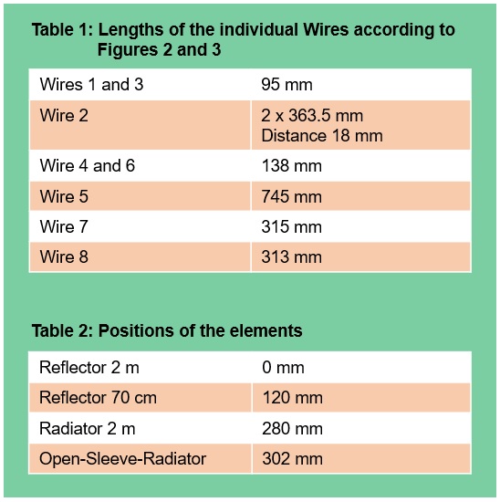
It is important that the length and distance specifications according to Tables 1 and 2 refer to the centre of the elements. If you deviate from this, the antenna will quickly be off by up to 1 MHz. With a 25 mm PVC installation tube, and the appropriate clamps, a remarkably light construction that can also be dismantled can be achieved.
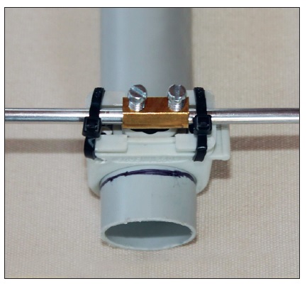
Figure 4. Connection and mounting the reflector
Since the reflector length exceeds 1 m, I solved the problem by connecting two halves with a clamp. Figure 4 shows this method. To fix the reflector in the feed point, the clamps are again a good choice. To do this, bend the radiator pieces inwards at right angles. The coaxial cable is attached directly, without a socket, and wound up into a feed choke, as shown in Figure 5.
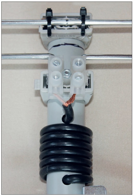
Figure 5. A clamp is placed at the feeding point of the antenna. Photos: DK7ZB
To give the frame the necessary rigidity, I have slipped plastic tubes over the ends of each element. If you use the antenna for permanent outdoor installation, you must install the feed point in a box, or protect it with hot glue.
Results
Adjustment is limited only to the distance of the 70cm Open-Sleeve-Element. If the resonance frequency is a little too low at 2m, it can be shifted upwards by a few 100 kHz by placing the Moxon reflector a little further away. This also increases the gap between the ends of the elements.
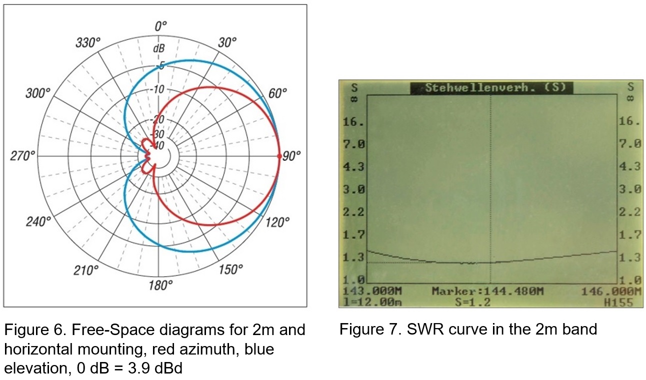
The gain on 2m is 3.9 dBd and is thus just below that of the popular HB9CV. The Free-Space diagram (Figure 6) shows a large horizontal 3 dB opening angle of 78° for a SWR at 144.3 MHz s = 1.2 and remains s < 1.4 throughout the band, according to Figure 7.
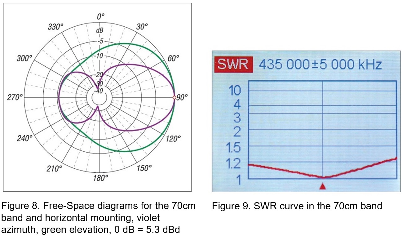
On 70cm, the standing wave ratio is particularly good, with no increase in the middle of the band, as Figure 9 illustrates. The 70 cm azimuth diagram, Figure 8, looks somewhat peculiar. The reason for this is the 3/2 λ resonance of the Moxon frame, which is partly included in the directivity. The gain here is 5.3 dBd.
The extremely high front-to-back ratio of the Moxon antenna at 2m is always astonishing. A beacon signal of just under S9 almost disappears in the noise when the antenna is turned 180°. With the data shown, operation is possible in the SSB and CW portions of both bands.
Vertical mounting for FM operation is also possible and can be the desired orientation of the antenna. The aperture angles of 141° and 114° are comparatively large in this case and the bandwidth is completely sufficient for both frequency ranges.
I also used EZNEC to check the performance when the antenna was stacked. For the 2m band, the distance of both antenna must be 1.6 m. Even this is too large for the 70cm band, the analysis still shows a gain of 3 dB when the antennas are stacked. If 2 × 3/4 λ coaxial cables with 75 Ω characteristic impedance are used for this purpose, they transform correctly with a 9/4 λ length even on 70cm, and problem free dual-band operation is possible with a stacked version.
Literature and sources
[1] Maguire, D., AC6LA: Antenna modelling Software and other utility programs. https://ac6la.comÆ Moxgen – Moxon Rectangle Generator
[2] Steyer, M., DK7ZB: Der Zweielement-Moxon-Beam. FUNKAMATEUR 58 (2009) H. 3, S. 284–288.
©www.funkamateur.de2021
This article has been translated by the FB NEWS Editorial section with the permission of the author and Box 73 Amateurfunkservice GmbH, the publisher of FUNK AMATEUR.
Topics from Around the World backnumber