


Special article, Part 2
Building an SHF Discone antenna
Completed 5.7 GHz Discone antenna
In the previous issue, I built a Biconical antenna using a LiteVNA (Vector Network Analyzer). Although I have not yet conducted any actual communications with this antenna, I again challenged myself to build a Discone antenna for on-air use in the SHF (Super High Frequency) band in the near future. This antenna also has an ultra-wide bandwidth like the Biconical antenna, and it is suitable for the SHF band, which has a wide bandwidth.
What is a Discone Antenna?
“Discone” is a coined word consisting of “disc” and “cone,” and can be said to be an antenna consisting of a “disc element” and a “cone element.” As shown in Figure 1, the disc is attached to the top of the antenna and the cone is attached to the bottom.
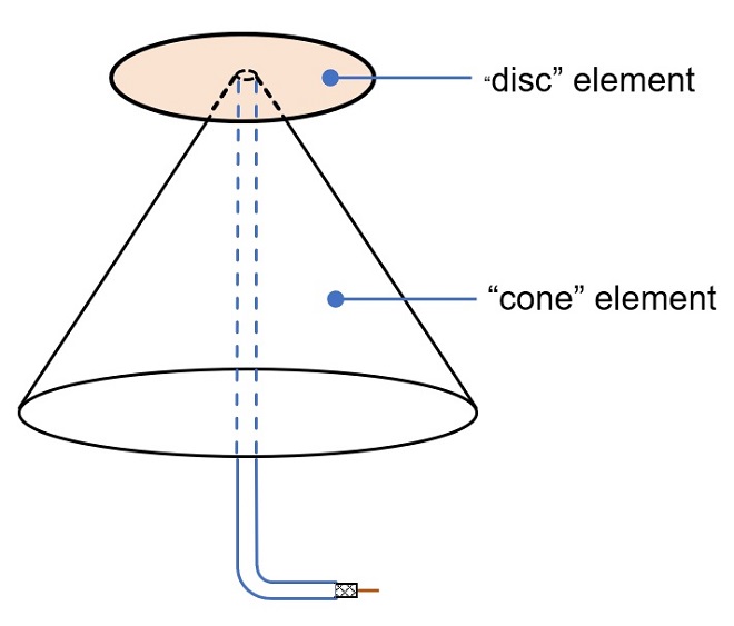
Figure 1. Discone Antenna Appearance
A book I have explains that the dimensions of the Discone antenna are determined by the lowest operating frequency. The length of the cone sides should generally be at least 1/4 wavelength above the lowest operating frequency. In this way, the input impedance characteristics are almost constant over a factor of 8 or more times the frequency, and ultra-wideband characteristics can be obtained.
Discone antenna fabrication
Specifications should be determined in the beginning. The center frequency of the antenna is set to 5.7 GHz, and the minimum operating frequency is set to 2.4 GHz (2400 MHz). According to the theory, the input impedance is almost constant up to 8 times the minimum frequency, so if all goes well, I may be able to use the antenna up to 19 GHz, which is 8 times the frequency band of 2.4 GHz. I will check this later as well.
The wavelength (λ) at 2400 MHz is 0.125 m (=125 mm) from the following equation.

Since the length of the cone's sides should be at least 1/4 wavelength of the lowest frequency used, the length of the sides, L should be 125÷4=31 mm. 31 mm or more should give results in theory.
It pains me to explain the result at the planning stage, but when I built the antenna with these dimensions, the SWR did not decrease over the wide bandwidth, and unfortunately, the result did not match the theoretical one.
In the end, after cut-and-try, I lengthened the length of the cone side (L) to about twice the calculated value, and after devising the distance between the disk and the cone, and so on, I set L = 68 mm, and as shown in Figure 4, the characteristics became constant over a very wide bandwidth. Therefore, I will proceed with the fabrication of this antenna based on actual measurements.
First, a copper plate and sheet are prepared like the biconical antenna fabricated in the previous issue. In this antenna, the copper plate used for the disk part of the upper element is 0.3 mm thick, and for the cone part of the lower element, a 0.1 mm thick copper sheet was used for ease of fabrication. The dimensions of each element are shown in Figure 2.
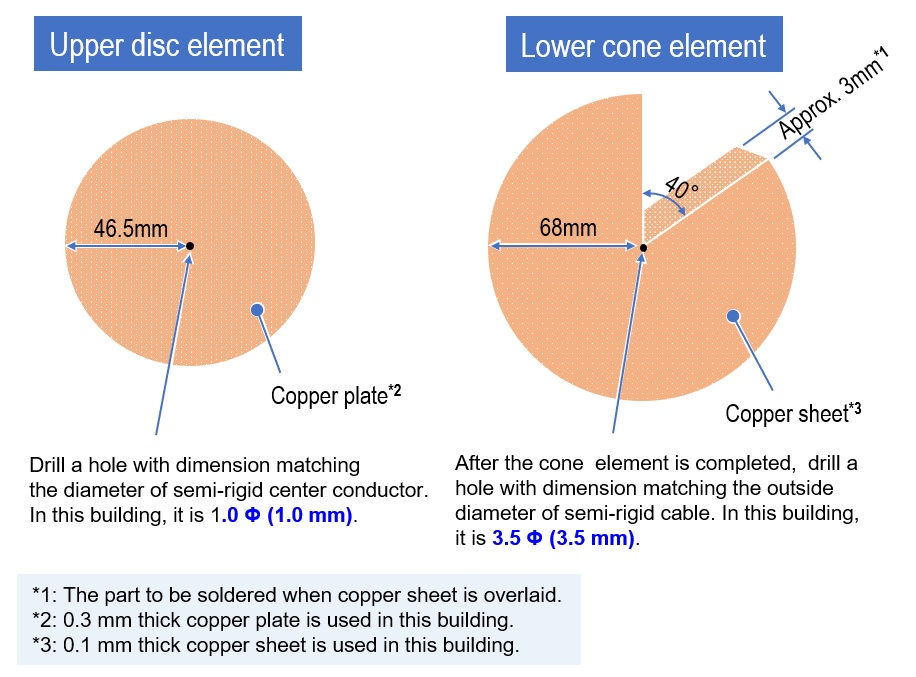
Figure 2. Dimensions of each element
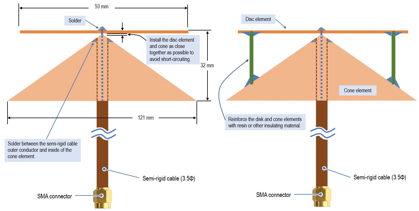
Figure 3. Joining each element
Characteristics of the completed antenna
The measured data is shown in Figure 4. In the image, “Start” is 1 GHz, “Stop” is 16 GHz, and the width of 15 GHz is shown. The antenna was fabricated for a lowest operating frequency of 2.4 GHz, but Since the edge length L of the cone is longer than the calculated value, both return loss and SWR characteristics are low from 1 GHz to 16 GHz, and thus, sufficient usable characteristics have been obtained.
The measurement also confirms the statement that the input impedance characteristics are almost constant over a frequency ratio of 8 times or more by making the length L of the cone of the Discone antenna at least 1/4 wavelength of the lowest operating frequency.
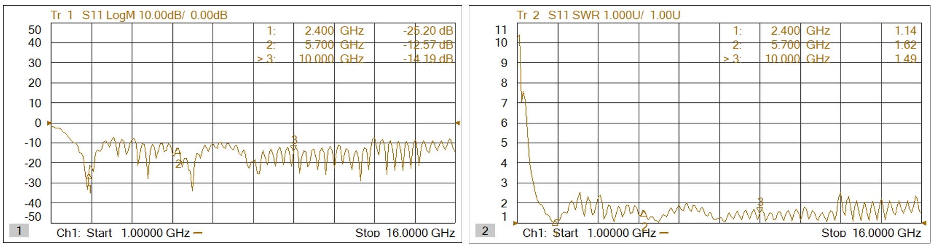
Figure 4. Measurement results (Left: return loss, right: SWR characteristics)
The radiation beam launch angle was also measured in one direction only, using a simple method. At 2.4 GHz, the main beam is pointed downward at an angle of about 45 degrees. At 5.7 GHz, it is almost horizontal to the ground, and at 10 GHz it is not clear which is the main beam, and which is the side lobe, but two beams are output. At 10 GHz, we do not know which is the main beam and which is the side lobe.
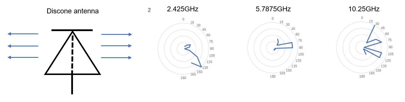
Figure 5. Simple measurement of the launch angle of the Discone antenna
Completed antenna with additional waterproofing measures
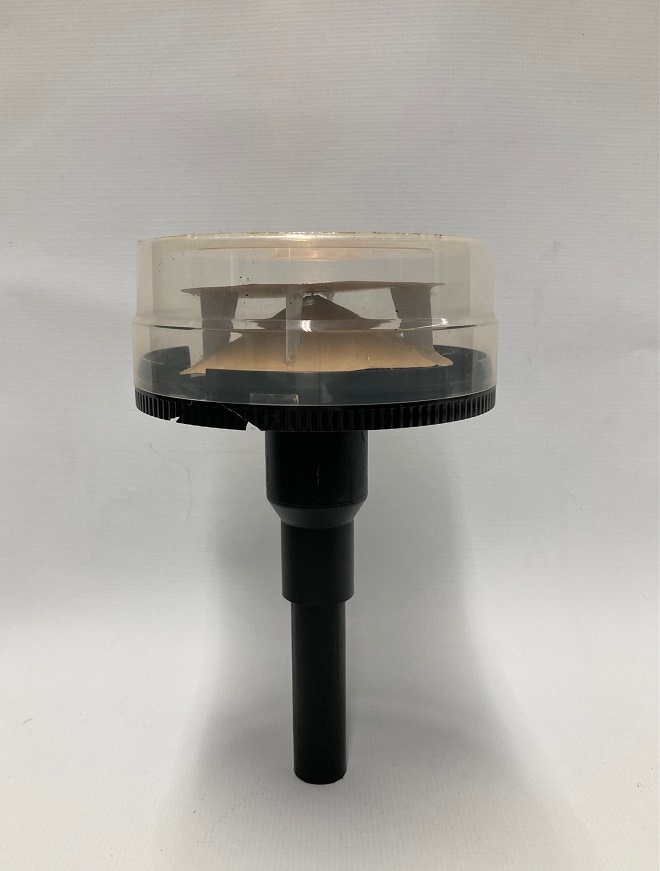
The completed Discone antenna is installed in a CD case, as shown in Figure 6. In this way, the antenna can be used as an all-weather antenna. The mast attached to the bottom of the CD case was made from a PVC pipe joint used for plumbing. After the antennas are installed in the case, the gaps are filled with adhesive to provide waterproofing.
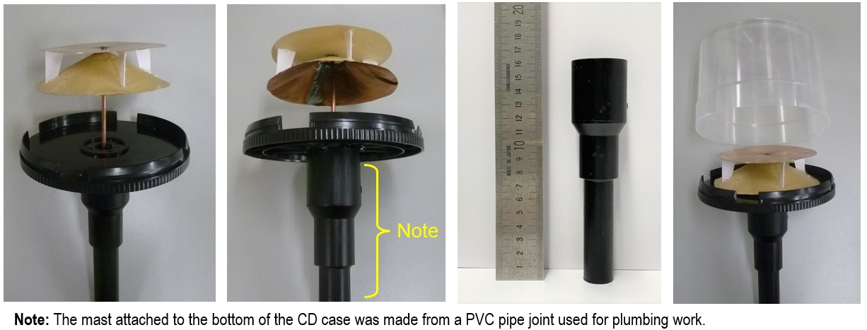
Figure 6. Discone antenna in a CD case
I disassembled a used GPS antenna I found at a junk market and installed the antenna I made in it to make a full-fledged SHF antenna (Figure 7). I will report the results of the measurement and operation as soon as they are available.
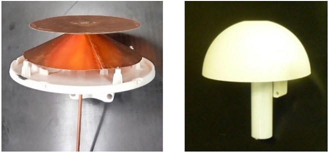
Figure 7. Discone antenna in case of used GPS antenna
OUI