


Technical Segment
My first impression of the Icom AH-730
I had an opportunity to use and test the AH-730, an automatic antenna tuner (hereafter called ATU) announced by Icom Inc. in March of 2022, in a mobile operation.
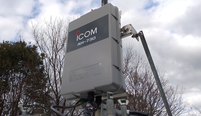
Icom’s ATUs for long-wire antennas, the AH-4 covers the 3.5 to 50 MHz bands, but the AH-730 additionally has the 1.8 MHz band, and so covers the bands from 1.8 to 50 MHz. I have confirmed the tuning speed on each band. I also tested the propagation of radio waves during actual operation with the AH-730 using the Reverse Beacon Network (hereafter called RBN). Let us start by introducing the specifications.
Comparison chart of each model
The table below shows the specifications for the latest model of AH-730 and the earlier AH-4 and the AH-3 models.
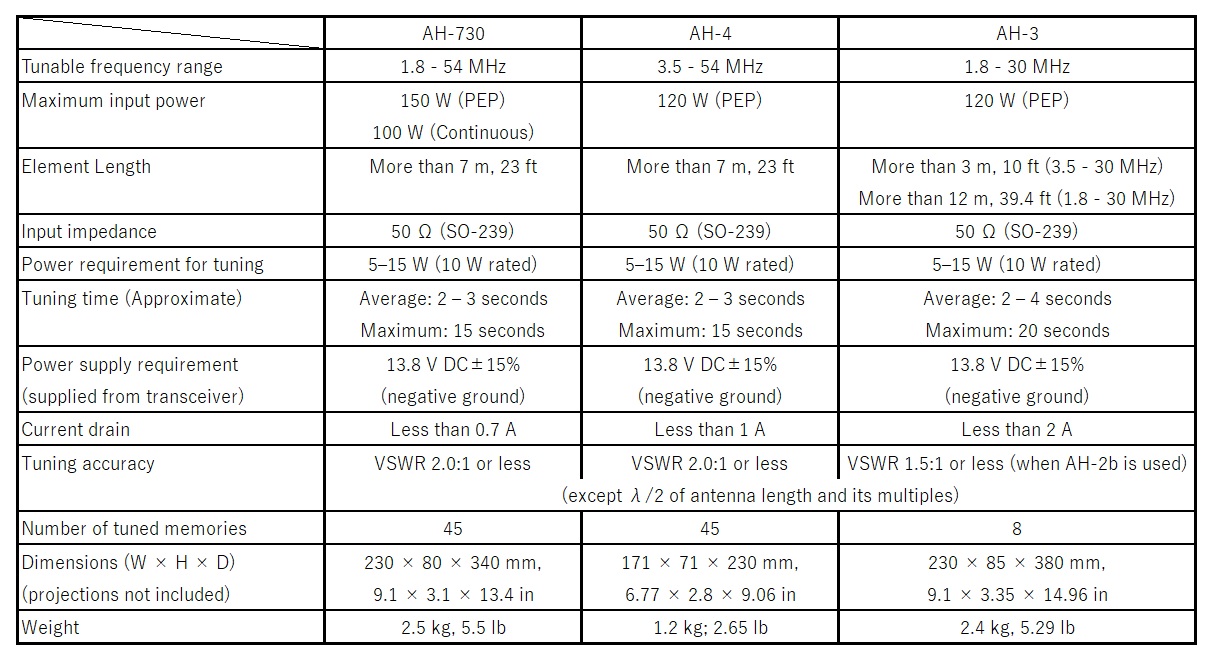
Table 1. Comparison chart for each model (Quoted from their instruction manuals)
Comparison of electricity specifications with other two models
There are two major differences between the AH-730 and the other models. One is that the frequency range has been widened to 1.8 to 54 MHz. The other is that the maximum rated input power has been increased from 120 W to 150 W. With the maximum input power rating of 150 W PEP, it can now be operated in any band or mode with a margin of safety, including the heavy duty FT8 mode with 100 W. The element length is a minimum of 7 m and supports 1.8 to 54 MHz, making it possible to simply and compactly go on-air in the 1.8 to 50 MHz band by connecting the AH-730 to a 100 W device such as the IC-7300.
Comparison of appearance with other models
In terms of external dimensions, the AH-730 external size is approximately twice compared with the AH-4. This is due to the physical size of the internal components relative to the increased frequency coverage and input power. However, when the AH-730 is compared with the AH-3, which also supports the 1.8 MHz band, it is slightly smaller, so there should be no problems with installation or transportation. The same applies to the weight, which is approximately double that of the AH-4 and slightly heavier than that of the AH-3. This is due to the larger external dimensions, but also due to the increase in weight caused by the higher rating, which is also not considered to be a major problem in terms of use.
Note: The author's style of operation is almost 100 % mobile operation, so it is stated that the increase in size and weight has no impact, but this is a personal opinion.
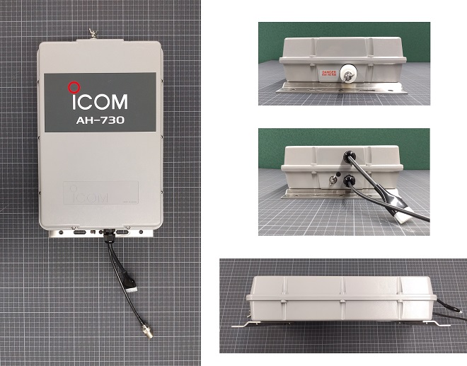
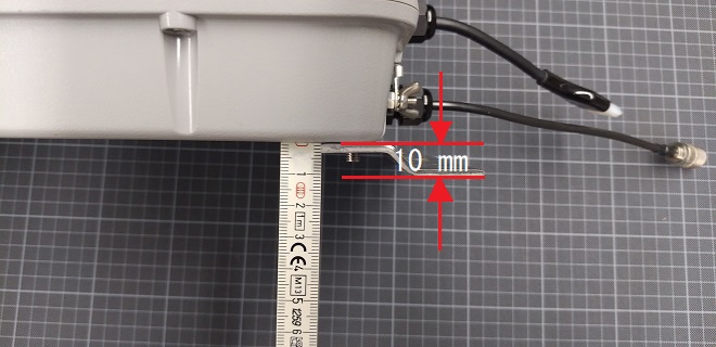
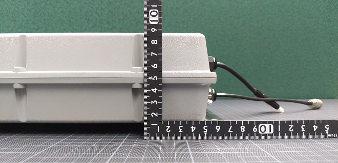
Outside appearances from each side
Coaxial and control cables can be connected to cables for coaxial cable (20 cm) and control cable (10 cm) outside the enclosure without opening the cover in the AH-730. Refer to the picture above for the externally cables. This prevents the waterproof gasket from getting damaged and ensures that the waterproof protection rating IPX4, which is a feature of the unit, and the ATU is protected as long as the cover is not opened.
The AH-730 is designed to be installed using M6 size bolts and nuts to secure it in place. U-bolts and mast clamps are also included, so unless it is a special installation, the accessories can be used for installation. (The author used the supplied U-bolts for the installation). The mounting bracket is made of 3.0 mm thick stainless steel, as shown in the picture below, and unlike the 1.5 mm used by other products, there was no deformation of the bracket or distortion of the cover of the unit to leave a gap when the nut is tightened. Other specifications are similar to those of the AH-4.
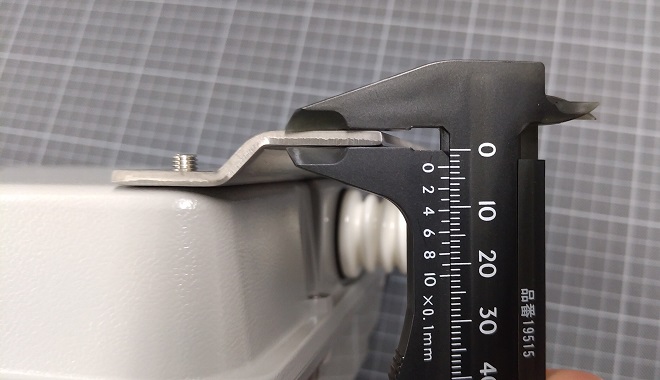
Thickness of the mounting bracket: 3 mm.
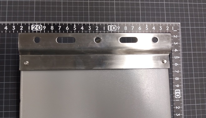
Width of the mounting bracket: 210 mm.
Element length
You first need to prepare the element as a long-wire antenna. I decided to use a fiberglass fishing rod to support the element and try to use it as a vertical antenna. If the length of the element is a half wavelength, or an integer multiple thereof, the feed point will have a high impedance and therefore cannot be matched. To avoid this, the lengths of the element in each band were calculated, as shown the diagram below.
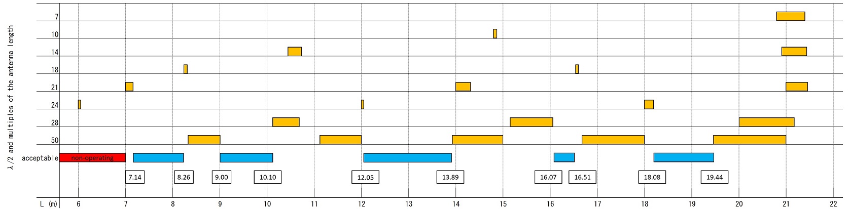
When calculating the element length, the minimum length was set at 7 meters based on the specifications of the AH-730, and up to 21 meters, which would be used in practical operations. As the minimum length of elements that can be connected is 7 meters, if the calculated length is less than 7 meters, it is marked in red as out of specifications. The lengths of half wavelengths, and their integer multiples calculated from the upper and lower frequency limits of each band, are marked in yellow. This means that the length of the element indicated in yellow for each band is not usable. Lengths that do not overlap with these yellow lengths are shown in blue. The lengths shown in blue are the lengths that can be tuned without problems. In this case, I decided to test the AH-730 with an element length of 7.14 to 8.26 meters, which is feasible with the fishing rods that I have. See the chart shown above. As you can see a red box in the left end of the chart, it is less than 7 meters long that is out of specifications.
Mounting and operations
Now that the antenna system was ready, I went out into the field to test in actual operation. As I had been using ATUs and mobile whip antennas in my car for mobile operation in the 1.8 to 50 MHz, installation was easy using U-bolts. For the grounding of the AH-730, I decided to connect a TBC* 22sq stranded wire with a large clip attached to it by clipping it to the existing HF grounding flat braided tin braided copper wire (TBC 22sq).
*TBC stands for Tined Braid Copper wire.
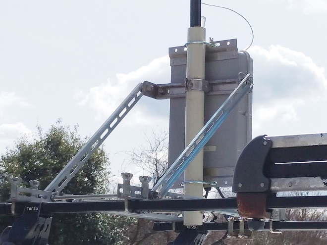
Antenna mounting base on the car roof
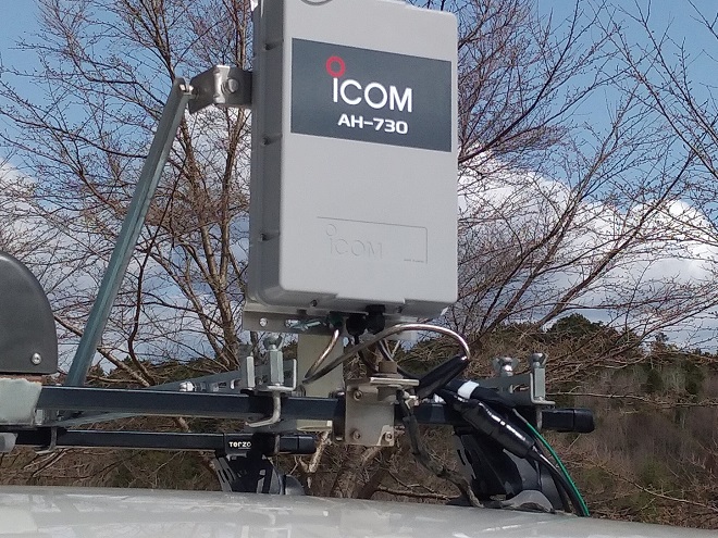
Grounding between the AH-730 and the existing car ground
The key is the fishing rod. I used one extended to 8 meters in length. This length is fine, as it covers the length of 7.14 m, which is the minimum length that I calculated.
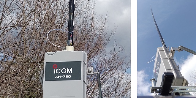
Mounting the AH-730 and the fishing rod to the mounting base
Now that the AH-730 has been installed on the car roof, I connected the IC-7610M (50 W version) installed in the car to the AH-730. The element and GND connections were tightened using wing nuts, so no tools were required.
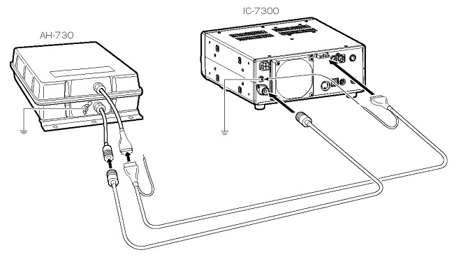
Example of connections of cables between the IC-7300 and AH-730
(Quoted from the FB News issued on March 15th)
To connect the AH-730 to the IC-7610M, I simply connected the coaxial and control cables as shown in the illustration above. The coaxial cable is connected to the ANT1 connector on the transceiver. The green wire coming from the control cable is the shield wire around the 4-conductor wire. This green wire is connected to the transceiver's ground terminal to prevent RF feedback. Once all connections had been made, I turned ON the transceiver and it automatically recognized that the AH-730 was connected to it. In this state, I pushed and held the [TUNER] button for about 1 second, and I could hear the click-clack relay sound for about 5 seconds from the AH-730 body. It then stopped and the tuning stopped. If the tuning did not stop, you would need to check the length of the element and the grounding of the antenna tuner. The ground should be connected to the antenna tuner and the vehicle body with the shortest and thickest wire possible to ensure grounding.
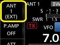
When the AH-730 is recognized.
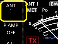
When the AH-730 is not connected.
I checked each band to see if I could get a tune for each of them. The length of the element was 7.14 meters, and I was very curious to know if it is possible to successfully tune, especially on the 1.8 MHz band. The result was that nothing went wrong, and it took only a few seconds to tune in the lower and upper band edges of each band. Although it took a little longer to tune in the lower edge of the 1.8 MHz band than in the other bands, but it still took only a few seconds. It seemed to be possible to get on-air on the 1.8 MHz band, with a minimum length of about 7 meters, as described in the instruction manual.
Next, I set the maximum length that the element attached to the fishing rod to 7.6 meters, which is not an integer multiple of 1/2λ. I was able to confirm that I could successfully tune on each band without any problems. Actual operation was carried out using this combination.
Operations with the AH-730
Actual operation was done by sequential changing bands from 50 to 1.8 MHz. The number of stations I worked with is shown in the table below. I operated in CW and RTTY on all bands, starting with 50 MHz after 15:00, and I started operating on 1.8 MHz around 19:00. Depending on conditions and operating times, I was able to work almost nationwide, from the northern island of Japan to the southern end. The transmitting conditions and reception were not inferior to those of the AH-4 I had been using, and I felt that the decoding rate was better on RTTY. I assume that this is probably due to a change in the radiation pattern compared to the previous system. The tuning was also good at 1.8 MHz and 3.5 MHz, where the element length was extremely short in relation to the wavelength, and the expected communication was possible.
The tuning was carried out in a location where there were no metal structures or power distribution lines in the vicinity of the element.
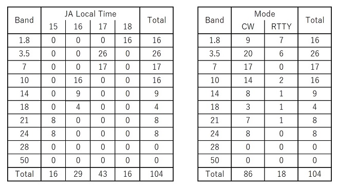
Left: Number of QSOs based on each operation band and time
Right: Number of QSOs based on each operation band and mode
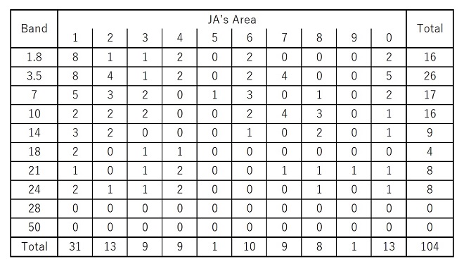
Number of QSOs based each operation band vs. area
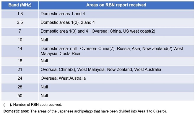
Next, I checked the RBN (Reverse Beacon network) to see how far my signals were reaching. The report below gives that information.
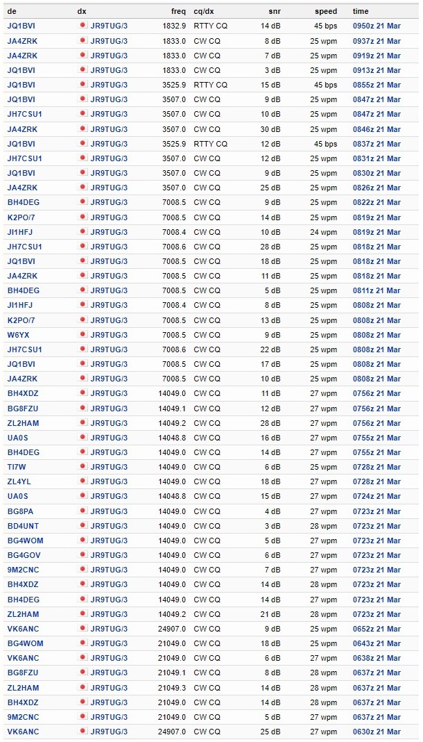
The report obtained from the RBN.
The reports I obtained can be summarized as follows, at each RBN spot. My impression was that for an element length of 7.6 meters, I thought the signal was reaching distant stations.
Summary
I tested the AH-730 on all bands from the HF high band to the HF low band, with an element length of 7.1 and 7.6 meters, which are the toughest conditions for the AH-730 to operate in. My impression from using it was that it worked fine, and I was satisfied the performance. I think it will make multi-band operation relatively easy, especially for those who have wanted to go out on 1.8 MHz but have not had the opportunity to do so due to the convenience of antenna installation, and for those for whom the installation of many antennas has been impossible.
The experiment was carried out with a 7.6 meter long element using a fishing rod. An attempt was made to lengthen the element further and try a 13 meter vertical aluminum element, but unfortunately it could not be used due to its weak mechanical strength. If I have an opportunity in the future, I would like to extend the length of the element and try other modes that were not used this time.
Technical Segment backnumber
- My first impression of the Icom AH-730
- PoE technology seen in the IC-SAT100M (vehicle-mounted type)
- How to operate the IC-705 with a desktop microphone
- Using IC-705 for satellite QSO from a ferry
- Find the gain of the stack antenna
- Antenna Technology Inc. releases WA72128 HF multiband dipole antenna
- IC-705 cooling experiment
- How long does the IC-705 battery last?
- Using the Icom AH-4 with the IC-705