


Technical Segment
PoE technology seen in the IC-SAT100M (vehicle-mounted type)
If you look at the product page on the Icom website, you will notice product names such as IC-SAT100 or IC-SAT100M, which were not found in the previous product series, among amateur radio devices and business wireless devices. If you read the product introduction, you will find that the product name "SAT" is the first three letters of "Satellite." Both are transceivers, but it is stated that the terminals do not communicate directly with each other, but rather through satellites, which are orbiting far above the earth. In this case, since there are no obstacles between the operator's terminal and the satellite, which interfere with communication, it is possible to establish stable and high-quality communication at all times by providing open visibility, even though the distance is far away.
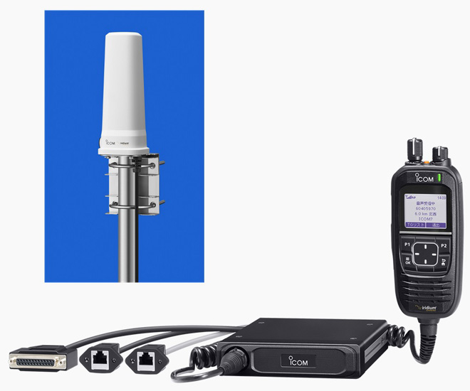
Figure 1. The IC-SAT100M using PoE technology, and its antenna (upper left)
You can see that the IC-SAT100M SATELLITE PTT (vehicle-mounted type) uses a very interesting technology. This technology is PoE (Power over Ethernet), which was explained a little bit in the October issue of Techinical Trivia by Dr. FB. There is some overlap with the previous explanation, but this time I will explain in detail the PoE used in this IC-SAT100M.
Connections between antenna and terminal
As 5G and 6G technologies in the world advance, it will inevitably require the transmission of large volumes of data, so the transition to the SHF band, which can secure sufficient bandwidth, will progress. When the frequency becomes high, in the case of business, it is necessary to use a waveguide in which radio waves propagate in space without using a coaxial cable, but I think that it will not become widespread in amateur radio because of cost.
The 2400 MHz band is one frequency band assigned to amateur radio. Even if we can operate on the band by connecting the coaxial cable between a radio and antenna, up to about 2400 MHz, the loss of the cable cannot be ignored in the frequency bands higher than that, and the RF power supply by the coaxial cable is no longer realistic. Therefore, let's consider a method of sending an RF signal to an antenna several tens of meters away from the main body of the radio without laying a coaxial cable.
If you connect the main body of the radio and the antenna without a coaxial cable, this is an extreme example, but it can be realized by doing as shown in Figure 2. As you can see, installing lot of cables makes it very complicated.
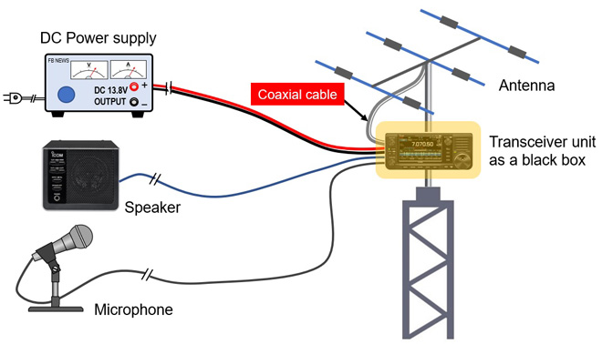
Figure 2. Unrealistic connection without coaxial cable
Coaxial cables are one of the major causes of creating losses in UHF and SHF. I think there are two main causes.
1. Conductor loss (loss with respect to DC resistance)
2. Dielectric loss (loss for alternating current between conductors)
Cause 1 above is the loss according to Ohm's law that occurs regardless of the frequency. However, the higher the frequency, the more the signal causes a skin effect in which only the surface of the conductor flows. In reality, the resistance value of high frequencies is higher than that of low frequencies, and the conductor loss increases.
Next, the dielectric loss shown in 2 above cannot be ignored in radio frequency (RF). Although it is a difficult word for a dielectric, we dare to call it an insulator here. An insulator such as polyethylene is used between the core wire and the braided wire of the coaxial cable. The resistance value is infinite in terms of direct current (DC), but when an RF is passed through it, a current will flow there due to the parasitic resistance, which will be a loss.
In short, passing high frequency RF through a coaxial cable causes more loss than passing lower frequency RF. In the UHF and SHF bands, the key point to suppressing loss is to make the coaxial cable part through which RF signals pass as short as possible. That's where the PoE technology mentioned at the beginning comes in. PoE is an abbreviation for Power over Ethernet. As you can guess from the meaning of the word, it is a technology that superimposes electric power (power source) on the LAN cable used for exchanging data between devices.
As shown in Figure 2 above, the system wiring is very complicated. When the LAN cable is used between the shack and the antenna for applying the signals of the speaker, microphone, the control signal of the transceiver and DC power to the transceiver unit installed under the antenna, wiring makes a very simple system.
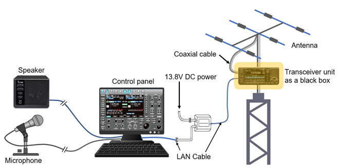
Figure 3. Realistic control panel and transceiver connected with a single LAN cable
When supplying DC power to media devices such as wireless LAN devices, and network cameras installed in places where it is difficult to supply DC power, such as outdoors or behind the ceiling, you can use PoE, which sends power to the LAN cable at the same time as the signal. It has the great advantage of eliminating the need for power source wiring for equipment.
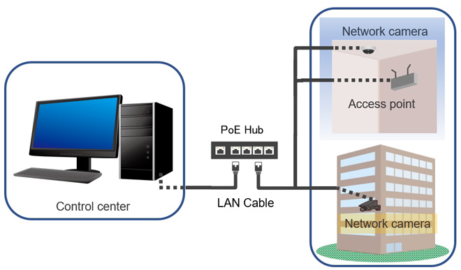
Figure 4. PoE connection between indoor and outdoor equipment
About the IC-SAT100M (vehicle-mounted type)
The IC-SAT100M is a wireless terminal (SATELLITE PTT) that uses the Iridium® satellite communication network. The Iridium® satellite system is composed of 66 orbiting satellites, located in low earth orbits 780 km above the ground, covering the entire world, including the polar regions. Amateur radio operators find the frequency of 1575.4-1626.5 MHz that is used very interesting. Communication with the partner station is performed through the low earth orbit Iridium® satellites, so real-time communication with less voice delay than other communication satellites is possible.
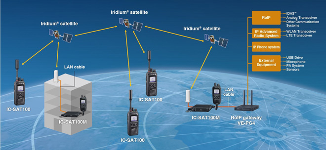
Figure 5. Communication system using Iridium satellites and wireless terminals
Unlike ordinary satellite phones, you can send voice to multiple parties at the same time just by pushing the transmit button (PTT button) like a transceiver, and communication is performed between satellites, stable communication can be ensured even if the ground infrastructure goes down due to a large-scale disaster. In addition, it can be used as a communication tool in places where communication infrastructure is not installed or properly maintained, such as remote areas and at sea, in cooperation with conventional radios and IP radios.
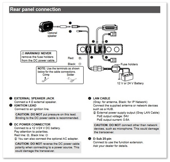
Figure 6. Rear panel of the IC-SAT100M (quoted from the instruction manual of the IC-SAT100M)
Looking at the rear panel shown in Figure 6, it is equipped with terminals that are different from ordinary transceivers. One of them is that although it is a transceiver, it does not have an UHF or Type-N RF antenna connector. The audio analog signal input to the microphone is converted into a digital signal by the radio unit itself and is sent to the antenna unit installed outdoors through a LAN cable, instead of a coaxial cable. (Figure 7)
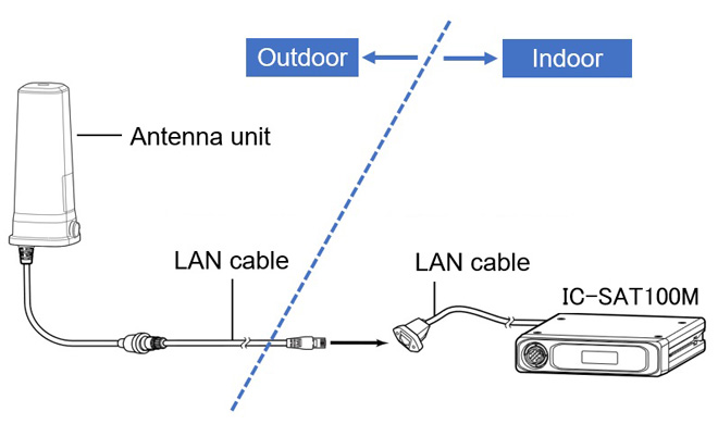
Figure 7. Connection between the transceiver unit and the antenna Figure
Supply DC power through the LAN cable
Considering the antenna unit in Figure 7, we can see that it contains an electronic circuit and a physical antenna. Simply put, it is an active antenna. Since it has built-in electronic circuits, it also needs DC power for operation. The IC-SAT100M supplies DC power to the antenna unit through a LAN cable. In network devices, LAN cables are used to connect devices, and PoE technology that supplies the DC power required for the operation of the devices with the LAN cable has already become popular. This technology seems to be usable for our amateur operation as well.
In the case of amateur radio, the control unit of the radio would be installed in the shack, and the main transceiver unit would be installed on a tower or roof. Even if the control unit and the main unit are connected with a 20 m long LAN cable, we need to consider the voltage drop of the DC power supply in the LAN cable. AWG24 to 26 wires are mostly used for CAT5e LAN cables that are commonly used. The DC resistance of these wires is stated to be approximately 100 Ω/km according to the AWG standard. From this information, you can calculate the DC resistance of a 20 meter LAN cable is 2 Ω. Since the signal needs lines for forward and return, the total cable length is 40 meters, twice the distance of 20 meters. In other words, the DC resistance is doubled to 4 Ω. The voltage drop of 4 Ω is 12 V, according to the formula of E = R × I if a current of 3 A flows through the cable. The voltage drop of 12 V is large, and the electronic circuit will not work properly, unless the voltage is increased.
Since the voltage drop in the LAN cable greatly affects the voltage supplied to the main unit, it is necessary to keep the current flowing through the LAN cable low in order to minimize this voltage drop. It is the same as a hydroelectric power plant built in a mountainous area, and it is very similar to transmitting the generated power to an urban area with a high voltage.
This can be summarized as follows.
(1) To reduce the power loss in the cable, it is necessary to lower the current value.Power loss = (current)2 x resistance value
(2) If the power consumption is constant, boosting the voltage can keep the current low.Power = voltage x current
(3) If the current value is low, the voltage drop that occurs in the LAN cable will also be low.Voltage drop = resistance value x current
PoE standard
There should be PSE (Power Source Equipment) which is a power supply side device, and PD (Power Device) which is a power receiving side device that receives the power supply in PoE. Both of them are connected with a LAN cable through a PoE compatible switching hub, and it is said that the distance that it can supply power is up to 100 meters. If you install a wireless device directly under the antenna, and connect it to a personal computer in the shack with a LAN cable, you can operate the wireless device from your shack without a coaxial and without considering the loss of the coaxial cable due to RF. It's very similar to what we amateurs think of as a remote shack.
The number of wires used in the LAN cable, and the thickness of the wires differ, depending on the LAN cable category. The cable we usually see is called Category 5e (CAT5e), which has 4 pairs (8) of wires inside. A signal, or a signal of transmission/reception timing is put on this cable to communicate between devices. PoE also has a worldwide standard. IEEE (called I triple E). The Institute of Electrical and Electronics Engineering has set PoE standards. Also, it seems that some private companies have their own standards.
As far as the table shown below is seen, there is no output voltage description of the supplied power, but the output on the power supply side is as high as 90 W according to the IEEE802.3bt standard. When the IC-705 operates with a 13.8 V DC power, the current consumption is about 3 A at 10 W operation, so the power consumption is over approximately 40 W. From this, we can see that the power of 90 W is very large. Each standard is posted for reference. In the table below, the top three rows are IEEE and the bottom three rows are private company-specific standards.
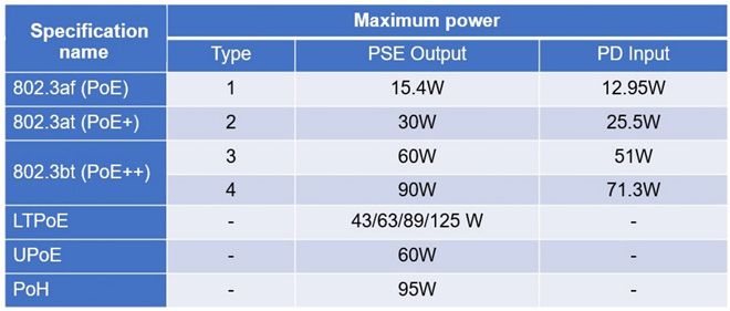
Figure 8. PoE specifications
Future development of PoE
In order for UHF or SHF technologies for amateur radio operators to be in a frequency band that many amateur radio operators can easily enjoy, it is necessary to develop radios that make full use of PoE technology as seen in the IC-SAT100M. In a previous issue of the Technical Trivia by Dr. FB technology explained the loss of coaxial cable to UHF, and it is considered that it can be applied to "Power supply," "Communication control," and "Image transfer," and so on.
The 2.4 GHz band is used for wireless LAN installed outdoors. Coaxial cable is not used for the antenna from the indoor terminal. Wi-Fi communication is performed from the indoor terminal to the access point, and the signal is sent as a data signal instead of an RF signal to just below the antenna installed in outdoor through a LAN cable. There is no RF intervening there, so there is no need to consider RF power loss. When the data signal sent through the LAN cable, the signal is modulated to RF by a device installed directly under the antenna. The RF signal can be radiated from the antenna almost without going through a coaxial cable. Also, there is no need for expensive coaxial cables.
If the image is as shown in Figure 9, it is possible to realize it in the amateur radio world by using the existing wireless LAN technology. An RF transceiver is placed as a black box directly under the antenna, and the signal received by the antenna is sent into the transceiver, converted to a digital signal, and then sent to the PC in the shack through a LAN cable. The transmit process is done in the opposite way. Especially in UHF and SHF, sending RF signals through a coaxial cable causes a large loss, so exchanging signals using a LAN cable is an effective method.
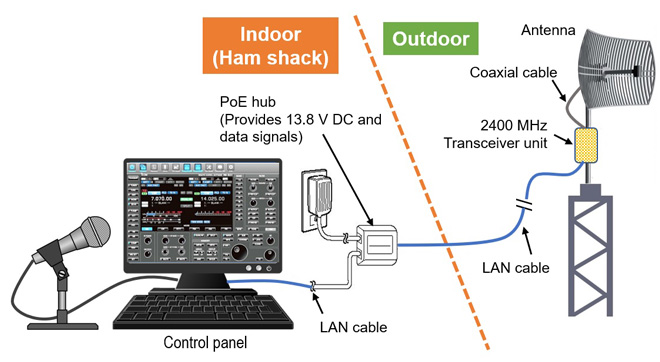
Figure 9. Image of the system connection with no coaxial cable
This method does not require complicated wiring. Signals are exchanged between the shack and the transceiver installed directly under the antenna, and DC power is also supplied only with a LAN cable. This time, I explained SATELLITE PTT using the Iridium satellite system used in the business world, but I am looking forward to explaining amateur radio using PoE in this corner in the near future.
FBDX
<Reference>
In the part that explains the frequency of wireless LAN in the text, it is expressed as "GHz" according to the explanation of 802.11b / g of IEEE, and in the part that explains the frequency band of amateur radio, it is expressed as "MHz" according to frequency allocations of Ministry of Internal Affairs and Communications of Japan
The PoE standard is quoted from the following site.
MACNICA
https://www.macnica.co.jp/business/semiconductor/articles/onsemi/133496/
System K Corporation
https://systemk-camera.jp/camera-blog/knowledge/highpower-device-poe.php
The illustrations on the computer are made by processing the free material of DESIGNALIKIE.
Technical Segment backnumber
- My first impression of the Icom AH-730
- PoE technology seen in the IC-SAT100M (vehicle-mounted type)
- How to operate the IC-705 with a desktop microphone
- Using IC-705 for satellite QSO from a ferry
- Find the gain of the stack antenna
- Antenna Technology Inc. releases WA72128 HF multiband dipole antenna
- IC-705 cooling experiment
- How long does the IC-705 battery last?
- Using the Icom AH-4 with the IC-705