


Short Break
Building a simple QRP power meter
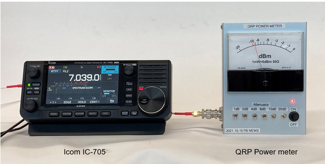
After using the IC-705, I woke up to QRP operation. Until now, I often operated with an output of 100 or 200 watt transceiver, so I do not have a power meter to measure 1 W or less. I made a simple QRP power meter with a maximum of 100 mW this time. It is not as accurate as a commercially available measuring instrument, but it can still be used as a guide to how many mW of power is being produced.
Overview of the QRP power meter
The principle is simple. Input RF power is alternating current, so you need to rectify the input signal with diodes as full-wave rectification. Then, amplify the signal with an LM386 Low-voltage audio power amplifier. Then, the amplified signal is shown with a current meter. Since it is a measuring instrument, it is necessary to calibrate with an accurate piece of test instrument before using it.
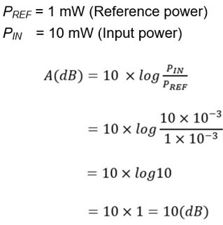
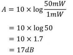
The power meter I build has a full-scale of 1 mW (= 0 dBm) under a 50 Ω load. If you input a 1 mW RF signal, the meter will show 0 dBm. For example, if you input a power of 0.1 mW, the meter will show -10 dBm. Also, if you input 10 mW, which is 10 times the RF power of 1 mW, the input will be excessive, and the meter will swing hard to the right, so first turn ON the 10 dB attenuator. When the 10 dB attenuator is turned ON, the meter shows 0 dBm according to the calculation shown below.
Six different attenuators, 1 dB, 2 dB, 4 dB, 8 dB, 10 dB, and 20 dB are installed just after the RF input connector. A 1/4 W metal film resistor is used for the resistors that makes up attenuators. Note that if you input more than 1/4 W of RF power, the resistors will burn up.
Insert the attenuation needed. For reference, 1 dB, 2 dB, 4 dB, and 8 dB are used because it is the same idea as BCD (Binary Coded Decimal), and numbers from 1 to 9 can be created by combining these four numbers. For example, when you want to have a 3 dB attenuator, the image is that attenuators of 1 dB and 2 dB should be turned on. It is a calculation that can obtain a maximum attenuation of 45 dB.
For the building of the attenuators, I used one introduced in the article "Fun Electronics Works 67th Variable Attenuator Part 2 (written in Japanese)" in a back issue of FB NEWS magazine.
Schematic diagram for the QRP power meter
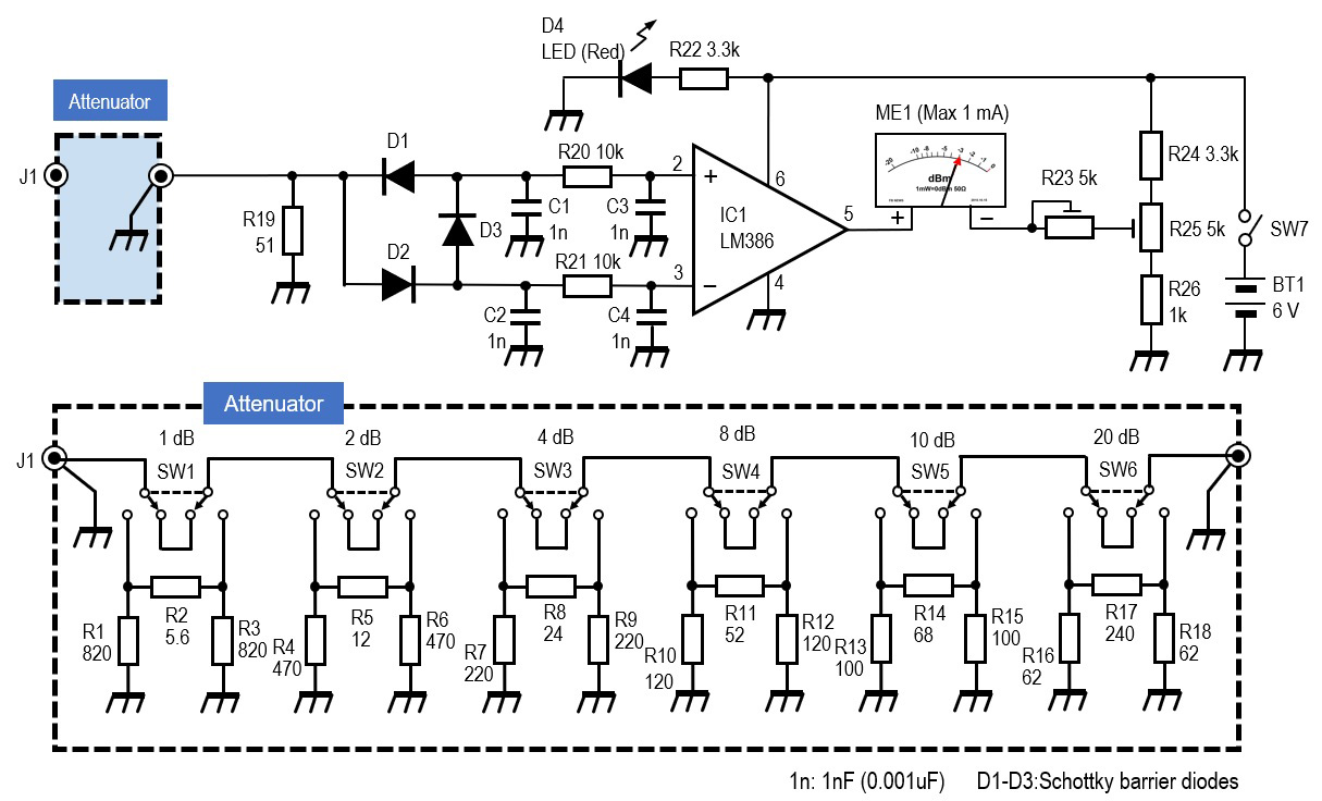
Figure 1. QRP power meter schematic (click to enlarge)
Circuit configuration of QRP power meter
(1) Sensitivity of the power meter
For having sufficient sensitivity on the meter, full-wave rectification composed of D1, D2 and D3 using Schottky barrier diodes with low forward voltage (VF). The VF of the Schottky barrier diode was 0.17 V. Considering that the VF of a silicon diode used for general switching is about 0.7 V, it is quite low. The meter used in the circuit is an ammeter with a full scale of 1 mA. I do not know the detailed electrical specifications, such as internal resistance. At 1 mW input, this 1 mA ammeter can swing the meter fully scale to the right.
(2) Zero-point adjustment
Due to the circuit configuration, even if there is no signal input to the LM386, there will be some voltage at the output terminal (pin 5) on the LM386, and the meter will swing. So, you need to have some ingenuity. The swing can be avoided by lifting the voltage on the minus side, balancing it with the voltage on pin 5, and adjusting the zero-point, instead of connecting the minus side of the meter directly to the ground. That is the circuit composed of R24, R25, and R26.
(3) Power saving
D4 is an LED that lights up when the power is turned on. Since this power meter runs on dry batteries, I wanted to reduce the current consumption as much as possible during use, so I chose an LED that shines brightly even with a small amount of current. Normally, a current of about 10 mA is required through the LED, but this time, a 3.3 kΩ resistor is connected in series to the power supply of batteries (1.5 V × 4 = 6 V), and it is lit at 1.8 mA.
(4) Building of the attenuators
As mentioned above, the attenuators used the information written in Japanese from an article previously published in FB NEWS. In order to make the attenuator as accurate as possible, the resistors were selected with a multi-meter by measuring each resistor, one by one. With an external 30 dB attenuator that can withstand a 10 W RF input, the measurement range extends from 0.1 mW to 10 W.
(5) Meter
An ammeter with a full scale of 1mA is used for the meter. Carefully remove the scale plate of the meter and replace it with the scale plate of dBm display made on a personal computer. The meter is a little large, 100 × 80mm, but it is easy to read the needle pointer.
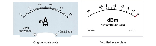
Figure 2. Replace the scale plate with the scale in dBm
(6) Case
I chose a case according to the size of the meter. The size of the case is 150 × 100 × 65 mm, and the material is aluminum. The inside of the case is anodized, so if you want to ground the case, remove the alumite with sandpaper.
Assemble
The electronic circuit was incorporated into a universal substrate with double-sided through-hole processing of glass epoxy, as shown in Figure 3 below. Since the RF signal flows from the BNC input connector on the board to the circuit that passes through D1, D2, and D3 to IC1, each lead-wire soldering should be as short as possible. For the attenuator part, a metal film resistor is simply soldered to the board, but if the space between each stage is housed in a shielded case, isolation can be obtained and a large amount of attenuation can be correctly obtained.
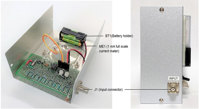
Figure 3. Inside and the input section of the completed QRP power meter
Adjustment and calibration
As I don't have a power measuring instrument, so I decided to make one. But in reality, I can't build a measuring instrument without a having a measuring instrument. The power meter is the same situation. I borrowed a standard signal generator, commonly known as SG, from a friend of mine and calibrated the meter.
There are two adjustment points, described below.
・Zero-point adjustment of the needle pointer when the power switch is turned ON.
・Full scale adjustment when a 0 dBm signal is input.
(1) Zero-point adjustment
・Switch off all attenuators.
・Record the position of the zero-point of the needle pointer.
・Turn ON the QRP power meter.
・No RF input signal is applied.
・Slowly rotate R25 to align the needle pointer with the scale of the zero-point (left end).
(2) Full-scale adjustment
・Switch OFF all attenuators.
・Set the SG output to 0 dBm (1 mW).
・Apply the SG signal to the QRP power meter through a coaxial cable.
・Turn ON the power of the meter.
・While slowly rotating R23, set the needle pointer to 0 dBm at the right end, full-scale.
・Set the SG signal to -10 dBm and apply it to the power meter.
・Confirm that the needle pointer points to -10 dBm.
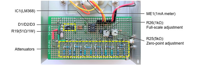
Figure 4. Internal board
Actual usage of QRP power meter
It is not an accurate power meter like the one on the market, but you can see that the power has doubled or decreased to 1/10. Now, let's measure the power using the Icom IC-705 Portable transceiver. Use the multifunction dial [MULTI] on the right side of the screen to adjust the power of the IC-705.
<Caution>
Do not directly input more than 100 mW of power. The internal attenuator will burn up.
(1) Confirmation of minimum power
The minimum power of the IC-705 is set to about 50 mW at the time of shipment. Let's check this.
・Set the IC-705 to the following:
・Frequency: Any frequency in the 7MHz band
・Mode: RTTY
・Output power indicator: “1%” (= 50 mW) using the [MULTI] dial.
Connect the input connector of this power meter to the antenna connector of IC-705 with a coaxial cable. Push and hold the PTT switch to transmit. This meter should point to 0 dBm with an input signal of 1 mW. Therefore, if 50 mW output power from the IC-705 is applied to this power meter, the meter pointer will go beyond the right-end. As shown in the calculation above, by turning on the attenuators for a total of 17 dB, that is, 10dB, 4dB, 2dB, and 1dB, the meter should show 0 dBm.
(2) Confirmation of 100 mW of IC-705
・Set the IC-705 as shown below.
・Frequency: Any frequency in the 7MHz band
・Mode: RTTY
・Output power indicator: Approximately 100 mW (2%)
In dBm notation, 100 mW is 20 dBm. If you input a 100 mW signal to this power meter in the same way as in (1) above, the meter should go to the right end, so first turn ON the 20 dB attenuator. When you push the PTT switch to transmit, the meter should point to 0 dBm.
(3) Arbitrary power measurement
If you want to measure the power over 100 mW, attach an external attenuator and input the power to the meter through the attenuators. By first attenuating to 100 mW (20 dBm) with an external attenuator, you can measure the power while looking at the conversion table of dBm vs. mW in Figure 5.
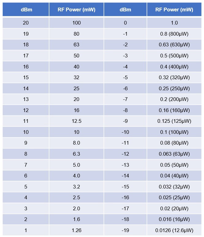
Figure 5. dBm vs. mW conversion table (click to enlarge)
CL
<Reference>
In building the main circuit of the power meter, I referred to the article of "Radio Project for the Amateur Volume 3" (Drew Diamond/VK3XU) and for building of the attenuator, I used the one introduced in the article "Fun Electronics Works 67th Variable Attenuator Part 2 (written in Japanese)" in a back issue of this FB NEWS magazine.
Short Break backnumber
- How many colors do you see when a colored disc is rotated at high speed?
- Making a dual Positive/Negative voltage power supply in a single box, for experiments
- Building of an RF Volt-Ammeter for QRP operation
- White noise generator project
- One day electronics project – Making a simple antenna tuner for QRP operations
- Can the RHM12 portable antenna be matched with a bicycle body on HF?
- Making an “ON AIR” lamp using LM358
- Making a simple anemometer
- Making a sound machine say “Good morning. Thank you for everything.”
- Electronics project for the 10 MHz reference signal generator (2)
- Electronics project for the 10 MHz reference signal generator (1)
- Making a straight type AM radio using a TA7642 IC
- About splitters
- Electronics project for FB NEWS: Making a decoration light string
- Making a Simple Electric Field Strength Meter
- Building a simple QRP power meter
- Building a 20 Amp electronic DC load device using an N-channel MOSFET for the load
- Building an automatic backup power switching unit
- Overvoltage protection device using LM358: Part 2
- Building an Over Voltage Protector: Part 1
- Making a 50 MHz monoband MLA without a variable capacitor
- Making a 50 MHz monoband MLA.
- Let's connect a computer headset to the IC-705
- Building a microphone selector
- Building an audio amplifier using an LM386 IC chip
- An External Keypad for Icom Transceivers
- After all, is the receiver good for Up-conversion?
- Find the gain of the stack antenna
- The mystery of controlling the microphone and PTT with only two wires
- RFID tag