


Enjoying Electronics Project
Battery isolator
It is convenient for your mobile operations.
When operating a radio on a mobile system, it is often necessary to get DC power from a vehicle battery. There may be problems such as the engine not starting due to inadvertent overuse in the situation. A sub-battery may be used for this reason, but it is convenient to charge the battery at the same time as the vehicle’s main battery.
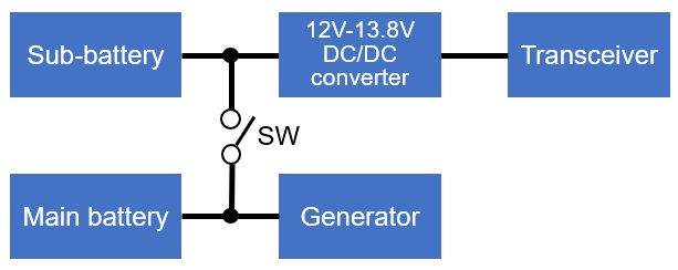
In this case, simply connecting an extra battery in parallel risks overuse, just as when operating with a single battery. Therefore, the vehicle’s main battery must be disconnected first to prevent this risk when the voltage drops.
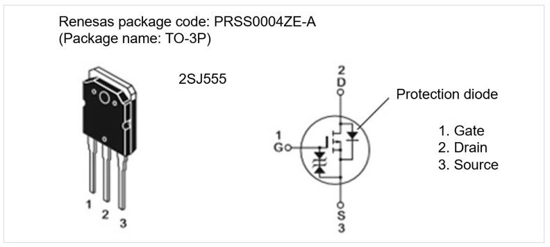
I wanted to use a semiconductor switch for this circuit, if possible, but after some research of the circuit, I found a difficult problem. When this switch is ON, I wanted to keep the voltage of both batteries at zero potential difference as much as possible. However, a current of 10 A or more may flow through the switch when the radio is transmitting, and with a transistor, a large current will leave a saturation potential difference of 0.6 V or more when the switch is turned ON. If I used an FET that can carry a large current, I may have been able to keep the potential difference a little lower, but the source (S) and drain (D) potentials are inverted when the battery is switched, so the protection diode inside the FET conducts and did not work as expected.
So, I had no choice but to use a mechanical relay. Fortunately, I was able to find a suitable 30 A relay by a mail order, and so I decided to use the one shown below.
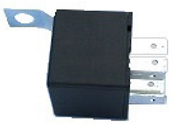
12 V operation, 30 A switchable mechanical relay
The overall circuit I have considered is as follows.
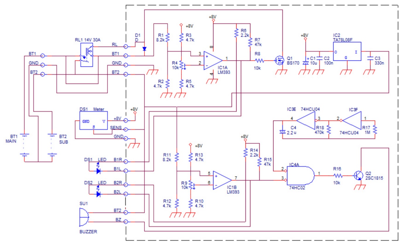
In the circuit above, BT1 is the main battery installed in the vehicle, and BT2 is the sub-battery added as the extra battery for mobile operation. The connection to the main battery is made at BT1 and GND. The connection to the radio is made at BT2 and GND. The main battery voltage is detected by IC1A. If the voltage from BT1 divided by R1 and R2 is higher than the voltage regulated by R4, pin 1 of the output of IC1A goes high, Q1 turns ON and relay RL1 operates to connect BT1 and BT2. Conversely, if the voltage on pin 3 of IC1A is lower than pin 2, pin 1 goes low, Q1 turns OFF, and RL1 is disconnected. The LED on DS1 will light up to indicate a low voltage on BT1 at that time.
The end-of-discharge voltage for lead-acid batteries generally seems to be 10.5 V. I set the voltage to disconnect the BT2 sub-battery from the BT1 main battery at 11.0 V for safety. If there is another suitable voltage, it can be adjusted.
If the voltage divided by R11 and R12 connected to BT2 is higher than the voltage regulated by R9, pin 7 of the output of IC1B goes high and Q2 remains OFF. If the voltage that time, a 0.44 Hz square wave created by the oscillator circuit, consisting of IC3E and IC3F, passes through IC4A. Therefore, Q2 is driven by this square wave and sounds the buzzer intermittently as an alarm. The LED on DS2 lights up at the same time.
The logic oscillation circuit that sounds an alarm buzzer consists of IC3E, IC3F, R17, R18, and C4, and the oscillation frequency is determined by the following formula.

R17 has no direct effect on the oscillation frequency. It is calculated to be about 0.47 Hz which is about once every 2 seconds. C4 has a large capacitance, so I wanted to use an electrolytic capacitor, but a bipolar capacitor with no polarity was necessary. A large ceramic capacitor with no polarity can also be used.
A 3-digit digital voltmeter displays and monitors the voltage of the BT2 sub-battery.

The alarm buzzer to warn of low voltage on the sub-battery is a simple electronic buzzer that works as long as a 12 V voltage is applied. It is attached to the rear of the case with double-sided tape.
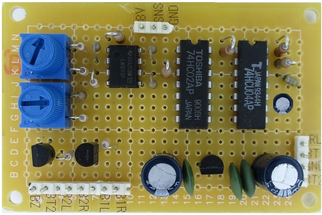
The main components were inserted and soldered to a 72 mm x 48 mm universal board, as shown in the photo below.
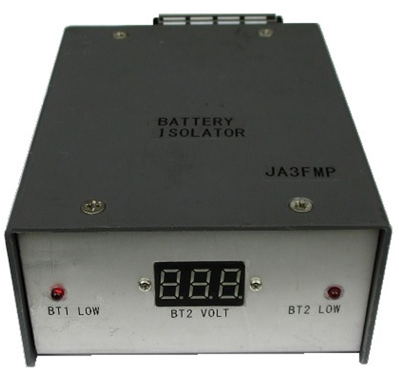
The unit is housed in a 90 mm x 120 mm x 50 mm aluminum case. The wiring to BT1 and BT2 may carry a large current, so I used a slightly larger terminal board. The outer case was also made large enough to accommodate them, but there is no particular part that generates heat.
The finished unit needs to be set up for voltage. Apply a 10.5 V that is for the end-of-discharge voltage to the BT2 terminals with a voltage regulated power supply. At this time, the unit's digital voltmeter should also read 10.5 V. Adjust R9 to set it at the very edge where the DS2 LED will light up and the buzzer will start beeping.
Adjustments related to BT1 are made by first connecting a 12 V battery or equivalent DC power supply to BT2. Connect a voltage regulated power supply with variable voltage to BT1. If 11.0 V is the voltage that separates BT1 and BT2, apply this voltage to BT1. Slowly rotate R4 to set DS1 LED to light and relay to turn OFF.
When set up in this way, if the battery voltage drops during operation, the connection between the batteries is first disconnected, and then an alarm buzzer sounds to notify the operator if the sub-battery voltage has dropped to the end voltage.
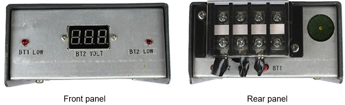
The front and rear panels are shown below.
I think that when we operate the radio with this unit and the sub-battery, we can operate it without worrying about the vehicle’s battery running out.
<Note>
This article was originally published in Japanese as "Fun Electronics Projects" in the December 2019 issue of FB NEWS by the author and has been translated by the editorial department.
Enjoying Electronics Project backnumber