


Enjoying Electronics Project
Voltmeter with alarm function
We often use 12 V lead-acid batteries for portable operations. In such cases, the battery voltage may become too low to be noticed and the radio may stop operating during communication. Therefore, I constructed a device that monitors battery voltage and issues an alarm when it falls below a specified value. This would also help to prevent the use of the in-vehicle car battery, being so absorbed in making contacts that the battery is used excessively, and the engine cannot be started after you finish operating.

Completed unit
The composition is as simple as the following.

Power is supplied from the battery to the radio, but some radios have significantly lower output power if the voltage is lower than the rated input voltage of 13.8 V, so it is safe to use a DC-DC converter to increase the battery voltage from 12 V to 13.8 V.
The voltmeter and alarm circuit are connected to the battery electrodes and displays this voltage on a digital voltmeter. When the battery voltage drops, the voltage is displayed, and when it falls below a preset voltage, an alarm sounds to notify the user. This circuit is as follows:

The voltmeter connected to the power input of this device displays its voltage. This voltmeter has a 3-digit digital display, which is sold in large quantities at parts stores, and is also used to switch to the lower limit voltage setting display of the battery. This voltmeter has three leads from the main unit for ground, power, and input, and has a wide voltage range for the power supply, making it convenient to just connect.

3-digit digital voltmeter
The regulator IC connected to the power supply outputs 8 V and is used as the power supply and REF for the IC and as a reference voltage. The end-of-discharge voltage of a lead-acid battery is about 10.5 V, although it varies slightly depending on the battery and load, so the alarm is set to go off when the battery voltage drops below this voltage. First, switch S1 to the "SET" position for the alarm operation and read the limit voltage set by the VR of R1 with a voltmeter.
Next, rotate R2 to the point where the DS2 LED switches from OFF to ON. When the switch is set to the "NORMAL" position, the IC goes into the standby mode, and the voltmeter will display the battery voltage. IC4 operates as a comparator. Under normal conditions, the voltage at the non-inverting input pin (+) of IC4 is higher than the inverting pin (-), so the comparator output approaches the supply voltage due to pull-up resistor R8. When the supply voltage falls below the set voltage, the comparator output is inverted, this time approaching zero.
At this time, the LED on DS2 lights up and the alarm circuit is activated. The alarm circuit is an oscillation circuit using IC1A and IC1B in a logic circuit, which oscillates at about 450 Hz according to f = 1/2.2CR. This signal is interrupted about twice a second by another oscillation circuit, IC1F and IC1E. The capacitors C2 and C6 must be non-polarized. The comparator and logic ICs are 4000 series CMOS logic ICs that work with an 8 V power supply.
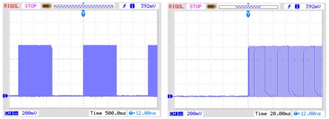
Output waveform (left) and magnified view (right)
Since the LM393 converter in IC4 has an open collector output, even when the output terminal becomes H level, the terminal does not output enough level of H. Therefore, R15 is added as a pull-up to the same terminal in parallel to make it H level. The output of the alarm sound is driven by power FET Q1 (BS170) and the sound is heard from the speaker. I was going to put the speaker inside the case at the beginning, but the dimensions did not allow me to fit it inside, so I had to pull out the lead wires and attach it to the outside. If an electronic buzzer is used, it is possible to remove the logic circuit including the oscillator, the speaker, and its driver.
An 8 V 3-terminal regulator IC was used for the LM393 in order to have a wide operating range. To assemble, the parts except for the voltmeter and speaker are mounted on a 72 mm x 42 mm universal board with the part where the power connector is to be connected notched out.

The case is a plastic case measuring 80 mm x 50 mm x 20 mm. The power supply connector is mounted on the opposite rear side of the case, and the speaker leads are also pulled out from this side of the case.
The circuit is simple and will work straightforwardly if the wiring is done correctly. The volume of the alarm sound output can be adjusted by changing the resistance value of R14. If you feel that the interval between alarm tones is a little long, shorten it by reducing the value of C2, C6, or R11.
<Quote>
This article is an English translation of a Japanese article that appeared in the March 2019 issue of the monthly FB NEWS.
https://www.fbnews.jp/201903/electronics/index.html
Enjoying Electronics Project backnumber