


Enjoying Electronics Project
You will be able to keep your desk clean with a multi-changer
It may be uncommon for amateur radio operators to use multiple radios. If microphones, CW keys, speakers, and so on, are connected separately to each radio, the desktop in your shack becomes cumbersome and you want to organize them. When operating a single set of radios, it is also troublesome to replace the microphones and CW keys each time the radio is changed. This time, I made a multi-changer that can be used with multiple radios by switching one set of accessories.
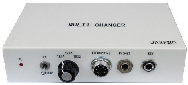
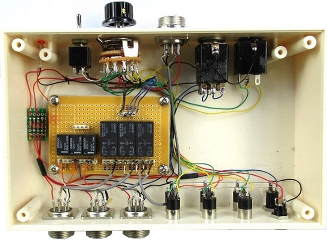
Completed multi-changer
The one I made is a simple one. I designed the circuit for Icom radios such as the IC-7800, IC-7300, IC-9100, IC-7000, and other radios I currently have.
I have made similar products in the past, but the biggest trouble I have had was with the microphone circuitry. In particular, due to the difference in ground potential between the radios, there were times when the connection of the microphones caused noise or audio corruption due to the location and method of dropping the ground side of the microphones.
There are two things that need to be switched when using multiple radios. One is the CW key, and one is the speaker. While I think there is little chance of RF feedback to the CW key and speaker, I decided to connect the GND terminal on the radio side securely because of the possibility of unexpected RF feedback due to differences in ground potential between radios.
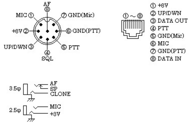
The microphone terminal connections of Icom radios to be connected is as follows.
I considered a configuration in which three radios are switched. Switching to each of the three radios can be done only with a multi-stage switch, if available. The switch I had was a 4-circuit, 3-contact rotary switch, so I used that.
The circuits to be switched are the microphone, CW key, and speaker.
The microphone switches between the microphone signal and its ground to avoid RF interference, and the CW key switches independent contacts between dots and dashes. The four circuits of the rotary switch are not enough, so I decided to use a mechanical relay as well. The relay is used to switch the two lines of the microphone circuit and the speaker, and the switch contacts are used for the rest. The overall schematic is shown below.
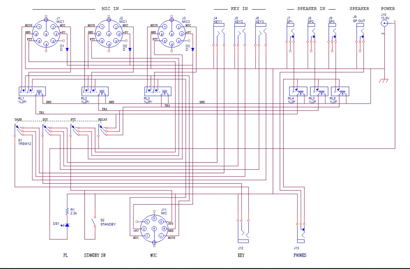
For the power supply of the relay, I initially thought of using +8 V from pin 2 of the microphone connector on the radio side. However, I found that the output current capacity is only about 10 mA, and the relay current is much larger, so I had no choice but to use +13.8 V from an external source.
Most microphones have a standby switch, and I also installed a manual standby switch on the unit.
The unit is assembled into a 175 mm x 110 mm x 40 mm plastic case. The front panel was fitted with a microphone connector, CW key jack, headphone jack, standby switch, and LED for a pilot light.
On the rear panel, I installed the microphone connectors, CW key jacks, and speaker jacks that connect to each radio.
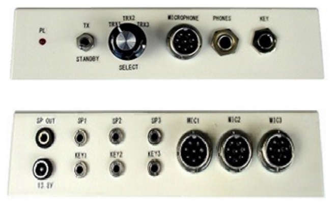
Front and rear panel layouts
The relay for microphone switching and the relay for speaker switching are mounted on a universal PCB for 47 mm x 72 mm size as shown in the figure.
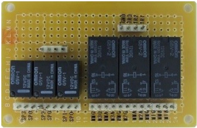
Wiring for each. Only the microphone circuit used shielded wire.
For the microphone signal line, I used a twisted pair of a LAN cable. I do not think you need to worry about using twisted pairs for other wiring. I am currently using a LAN cable for the microphone extension cord in the in-vehicle equipment installed in my car, but no particular abnormality has occurred
I also made three pairs of cables for the speaker and CW key, each soldered to a plug that matches the jack type. If you need a conversion connector from an 8-pin connector to a modular connector, Icom offers the OPC-589 as an optional cable.
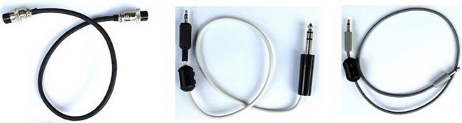
Cable for microphone Cable for CW paddle Cable for speaker
If you place the unit I made at an appropriate position on your desk, you will only need one set of accessories, instead of the three sets needed in the past, and you will be able to keep your desk clean. TU
<Note>
This article was originally published in Japanese as "Fun Electronics Projects" in the September 2019 issue of the monthly FB NEWS by the author and has been translated into English by the editorial department.
Enjoying Electronics Project backnumber