


Enjoying Electronics Project
Making a step attenuator
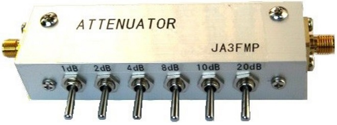
Completed step attenuator
I made a small, easy-to-use step attenuator. Let us consider a little about the attenuator. There are two types of attenuator circuits. One is a pi (π) type and the other is a T type. Either type is acceptable, but for the convenience of resistor installation as an electronics project, I chose the pi (π) type attenuator. The calculation of attenuation and each resistor value is as follows.
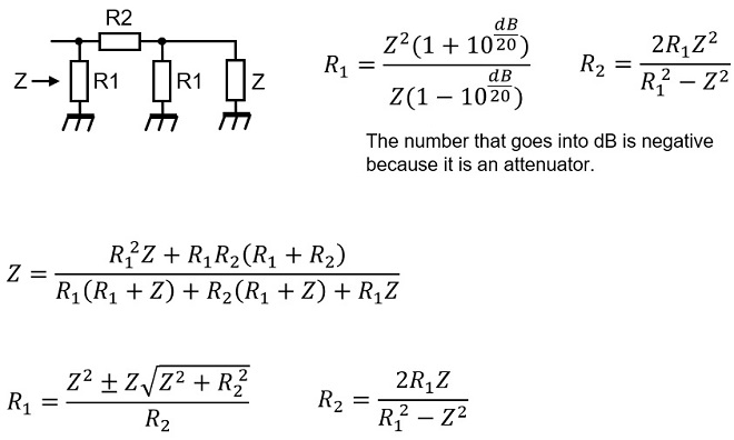
It is structurally difficult to ensure isolation between attenuators if an attenuation is set too high for the attenuator to be made. The step attenuator I built has 6 different attenuations in a metal case: 1 dB, 2 dB, 4 dB, 8 dB, 10 dB, and 20 dB. Turning ON each attenuator means that it can be set up to 45 dB in 1dB steps. The calculation results are as follows.
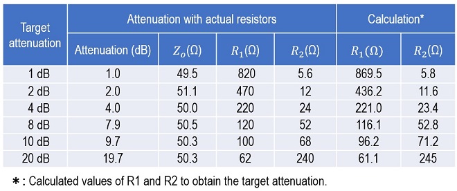
In this table, the numbers in the R1 and R2 columns labeled "Calculation" are the calculated values. The resistor values listed in the R1 and R2 columns are not actually available in parts stores. In short, those values are calculated resistor values.
The values in the column labeled "Attenuation with actual resistors" are the attenuation values when made with commercially available resistors and configured with the resistance value closest to the calculated value. Attenuation is calculated with this resistance value. Zo is the impedance calculated with these resistance values. It differs a little compared to the target value, but there seems to be no problem in practical use. The overall circuit diagram of this attenuator is as follows.
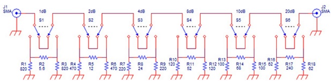
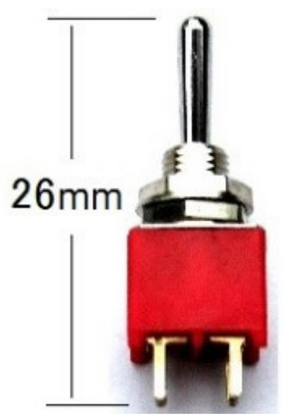
The resistors used were a chip resistor 1608 type (1.6 mm x 0.8 mm). They are very small. Since I had many of these resistors on hand, I measured several resistors with a measuring instrument and selected those that were within the allowed error, but close to the calculated value. For example, to obtain 1 dB of attenuation, commercially available resistors use R2 = 5.6 Ω, but the calculated value is 5.8 Ω. Therefore, even though the resistance varied from 5.58 Ω to 5.63 Ω, I chose 5.63 Ω, which is a little closer to 5.8 Ω. The switches are small 6P toggle switches for printed circuit boards, which I bought in bulk at a parts store.
The switches are first soldered to a 2.54 mm pitch universal PCB (Printed Circuit Board). The resistors are 1608 type chip resistors, each soldered to the pattern for wiring.
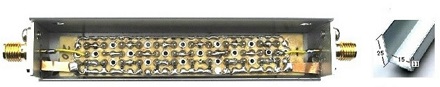
PCB built into the case
The case is made of aluminum. Two pieces of L-shaped aluminum material cut to 85 mm in length were made and placed on top of each other alternately. For the part to attach the SMA connector on the side, an L-shaped angle cut from the same material to 15 mm to fit the inside dimensions was used.
The front part has mounting holes drilled to match the pitch of toggle switches, and the switches were mounted. The SMA connectors on both sides were drilled according to their dimensions, but only two of the four mounting holes are diagonal. I also installed a thin copper plate for grounding in one hole.
When that it was done, I connected a tracking generator to the connectors on both sides and took measurements. The characteristics seem to be better than expected.
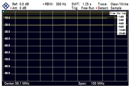
The yellow lines represent the attenuation with respect to frequency. The yellow lines represent -1 dB, -2 dB, -4 dB, -8 dB, -10 dB, and -20 dB from the top.
The attenuator I made was intended to be usable up to about 100 MHz. The characteristics depend largely on the chip resistors, but the ones I used seem to have good characteristics up to this frequency. Even chip resistors are not simple pure resistors at several 100 MHz, and their characteristics will vary. The frequency characteristics of the switch should also be considered, but it seems to be good up to about 100 MHz.
The maximum input power of this attenuator is about 100 mW because the resistors that I used are 1608 type chip resistors. A fixed power attenuator is required to handle higher power. Assuming that the transmitting power is 50 W, 27 dB of attenuation is required from 50 W to 100 mW. If the attenuation is 30 dB, a 20 dB/50 W and a 10 dB/2 W power attenuators will make the attenuation. However, these are expensive devices, but if you have them, they can be used in a wide range of applications.
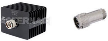
Fixed attenuator for 20 dB/50 W (Left) and 10 dB/2 W (Right)
(Pictures quoted from Pasternack Enterprises, Inc.)
Enjoying Electronics Project backnumber