


From Steve's Workbench
My shack was a jungle of cables!
The solution was a remote antenna switching system.
Hams sometimes say, ÔÇťYou can never have too many radios,ÔÇŁ but for some that wish applies even more to antennas. When we put up the first antenna, a single coax cable enters the shack and simply connects to the new rig. As more antennas are added, additional cables snake in toward the operating desk. Soon your shack might resemble the one below, and changing bands and antennas becomes an annoying chore.
Fortunately, this is a simple problem with simple solutions. Antenna switches and relays are a popular accessory, with many variations are available both ÔÇťplug and playÔÇŁ and for the homebrew builder. I found that building my own was a fun and inexpensive DIY project and resulted in much more enjoyable operation.
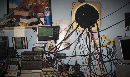
Figure 1. My shack was nearly as scary as this one.
My Antennas
For several years I operated on seven bands with only two antennas. Two feedlines connected to a manual ATU that had a 3-position antenna switch, so an extra connector was available for a dummy load.
After a bad case of Antenna Fever, new HF antennas appeared on my roof, and new cables snaked into the shack. I soon had more feedlines than the ATU could handle, plus control cables. My desk was a jungle, and changing antennas was a nuisance. My favorite activities were chasing SOTA activators and DX openings across the bands. I needed to make it easier and put the fun back in.
To improve matters, I made a patch panel so I could select which antennas and radios are connected to one another with coax jumpers. (Figure 2) This looks tidy, but the cables had to be disconnected and reconnected, taking time and prone to errors.
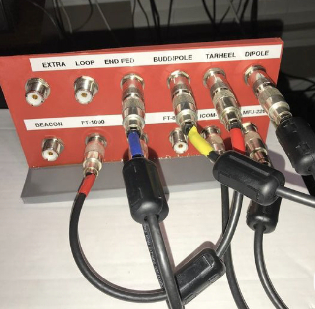
Figure 2. A coaxial cable patch panel
Manual coax transfer switches can also be used when there are not many antennas to select, but neither a patch panel nor a manual switch moves the cables very far from the desk. (Figure 3)
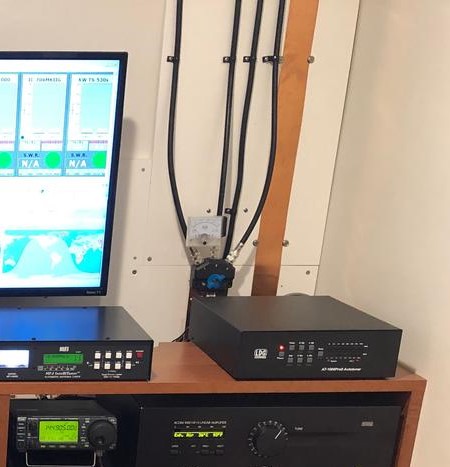
Figure 3. A manual antenna selector switch helps tidy the shack.
The Remote Switching Solution
With a remote antenna switching system, all the antenna cables come to a relay box some distance from the operating position, and the antenna is selected from a control box near the radio. In most applications the relay box is located outdoors near the antennas or on a tower. One cable can then feed several antennas, so avoids expensive multiple runs of low-loss coax. My goal was only to move the relatively short antenna cables away from the desk and switch them quickly, but the basic idea is the same. (Figure 4)
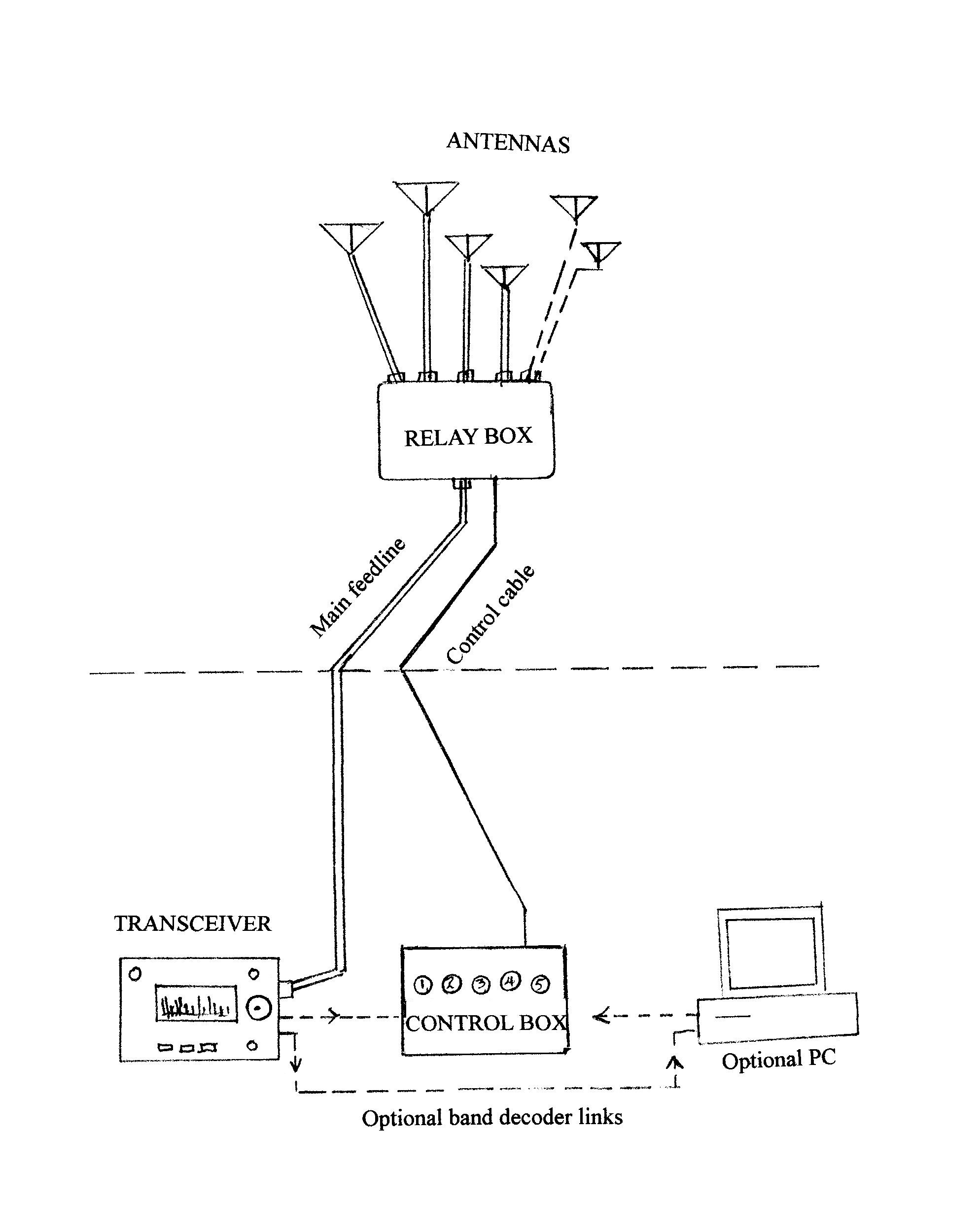
Figure 4. Basic layout of a remote antenna switching system
Commercial remote antenna switches are usually sold as a system, such as the desktop switch and relay box seen in Figure 5. There are many similar or more elaborate systems that can manually or automatically select from as many as ten antennas.
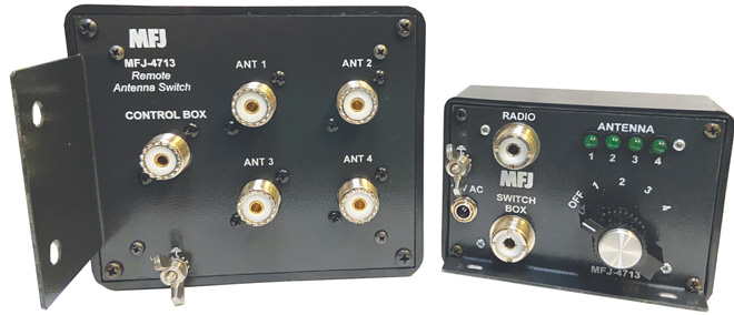
Figure 5. The relay box and the desktop control of a simple commercial system
As usual with the cost of ham radio gear, ÔÇťthe sky is the limit,ÔÇŁ but there are also inexpensive options for building your own system. You can decide on what works for you now and then change individual parts in the future.
The remote relay box is probably the most important part. Of course, it must be weatherproof to be used outdoors (Figure 6). Important parameters when selecting a coax relay are insertion loss and isolation. Most will also ground the unused connections for safety. Either open-frame or sealed relays may be used, depending on the power rating and other factors.
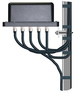
Figure 6. A remote relay box installation.
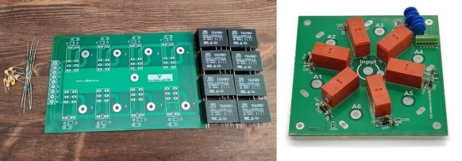
Figures 7a and 7b. Relay boards for homebrew systems.
For the homebrewer, partially and fully assembled relay boards are available from internet sources. Some use high quality relays that can handle up to 1500 watts. Examples are seen in Figure 7a and 7b. Relays and coax connectors can be mounted in standard outdoor electrical boxes.
For the control box at the operating position, the main choice is either manual antenna selection, or automatic selection by using band information from the transceiver or a linked PC. Commercial models can be as simple as that shown in Figure 5, or more complex and expensive if they do band decoding for automatic relay control. Two main band-selection protocols exist, with Yaesu and Elecraft using a digital (BCD) band signal, and ICOM and Kenwood using DC voltage levels. Universal decoders are now available, some of which can be programmed to provide special switched outputs, and others are specifically designed to control a remote station.
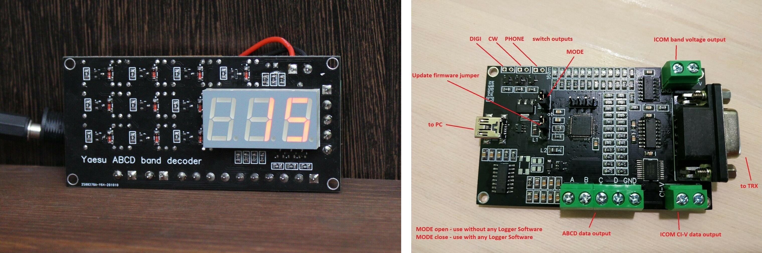
Figures 8a and 8b. Inexpensive band decoder modules
The last component is the actual link between the operating desk and the remote antenna relays. Simple manual controllers require multi-conductor cable, while others use serial digital control (RS-232). Wi-Fi or smartphone connectivity is another option.
Construction considerations
If you decide to build a remote antenna selector yourself, there are no special requirements for the components. The layout can suit your needs and the circuit design can be very simple and based around available parts.
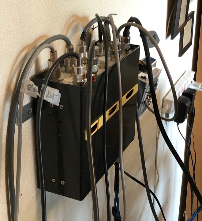
Figure 8c. Relay box on the wall behind my desk. The heaviest cable goes to the rig. Small openings reveal which relays are activated.
Whether using a manual switch or a relay, it is desirable to have low insertion loss, constant impedance, and high isolation, but compromises are often made in HF applications. Many transceivers and linear amplifiers use ordinary relays with direct wiring to the chassis connectors for transmit/receive. I used inexpensive 5-volt SPDT power relay modules having a clean layout and wide signal traces.(Figures 9a and 9b) They are not designed for RF but work well and simplify construction with on-board components such opto-isolators and LEDs. Their internal capacitance can be a problem at very high impedances, but I have tested them at 50 ohms with up to 500 watts. Figure 10 shows another homebrewerÔÇÖs relay box using high-power relays.
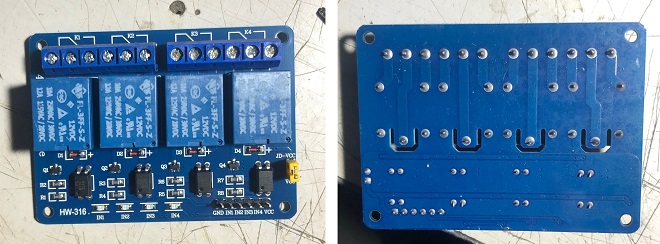
Figures 9a and 9b. Relays are actuated by grounding one header pin.
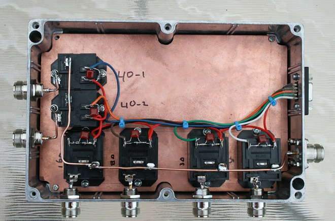
Figure 10. A DIY relay box for high power.
Manual and automatic band decoders can easily manage using one antenna for several bands, but it is more challenging to select one or two from several antennas for a given band, and then switch in a coupling network. These and other requirements led me to design a manual control system for the relays.
For the wall-mounted relay box I used an aluminum case intended from a 1960s vintage DIY portable transceiver. After removing the chrome handle and leather carrying strap, I mounted nine SO-239 and two BNC connectors on the top panel, leaving room inside for the relay modules, a DC power supply, the diode matrix board, and control connectors. This accommodated all my antennas, the ATU, dummy loads, with spare circuits for future antennas (!) or in case a relay fails.(Figures 11 and 12)
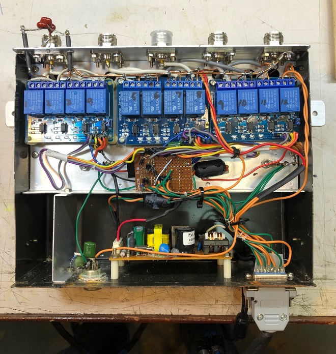
Figure 11. Inside the relay box. Steering diodes are on the perfboard.
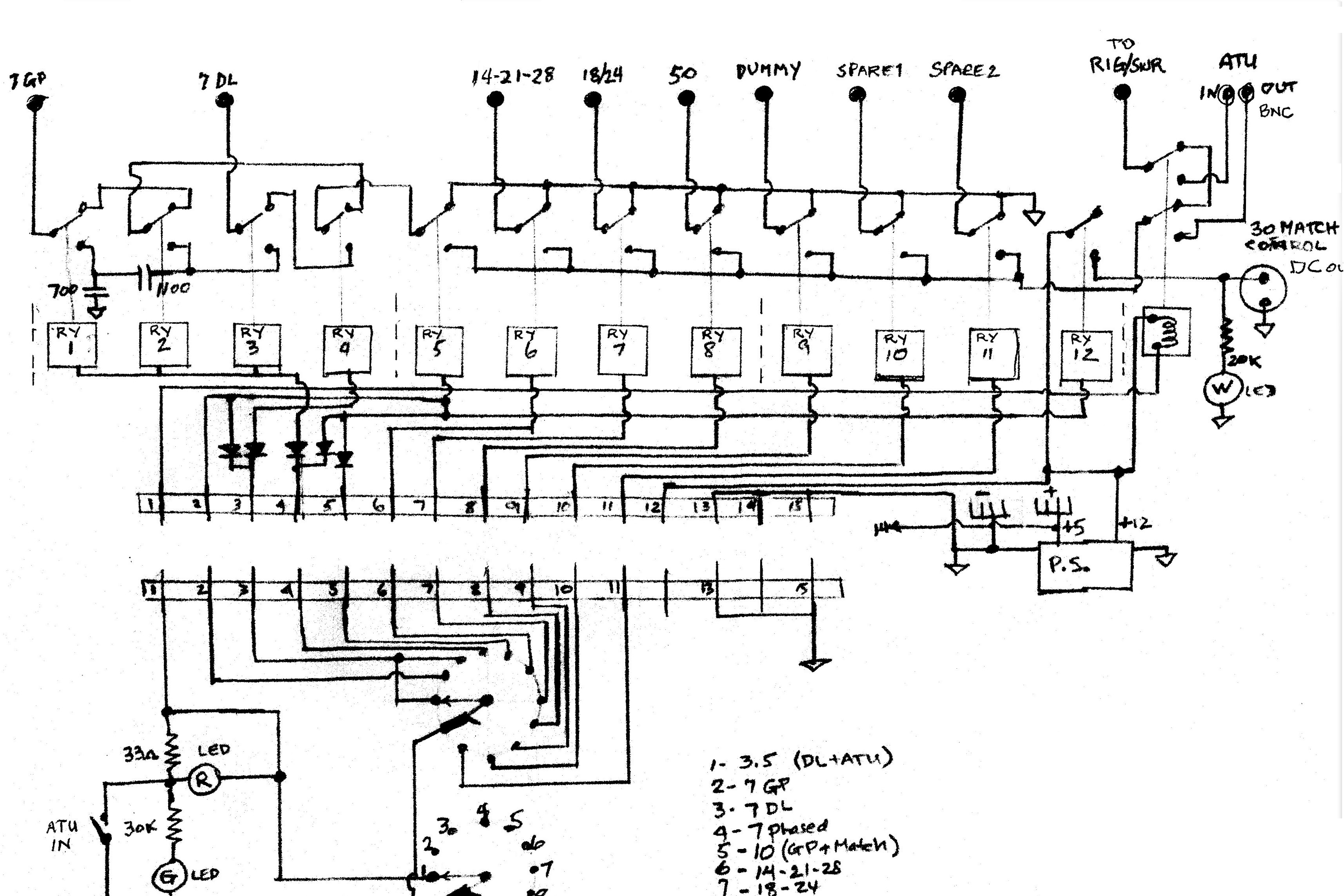
Figure 12. Schematic diagram of the antenna switching system.
Figure 12 shows most of the normally-closed relay contacts connected to a common ground buss, with the normally-open contacts going to the transceiver buss. Individual relay common contacts connect to the nearest coax input, as in the unit in Figure 10. This leaves the antennas grounded until connected to the transceiver. I will not go into detail about the circuit because the design is straightforward, and everyone will have different antenna switching needs. The stray capacitances are small but noticeable. VSWR into a 50-ohm dummy load is 1.1:1 at 20Mhz and 1.3:1 at 30Mhz, not as good as some commercial units but with no effect on operation.
An 11-position, 2-gang rotary switch in a small box controls the relays, connected to the relay box with CAT-5 cable. (Figures 13a and 13b) The second switch deck will simplify adding future functions. A diode matrix in the relay box allows combinations of relays for any switch position. It took five SPDT relays and five diodes to select either of my two 7-MHz antennas or combine them through a matching network. If you can program an Arduino or microcontroller, any custom relay controls will be possible.
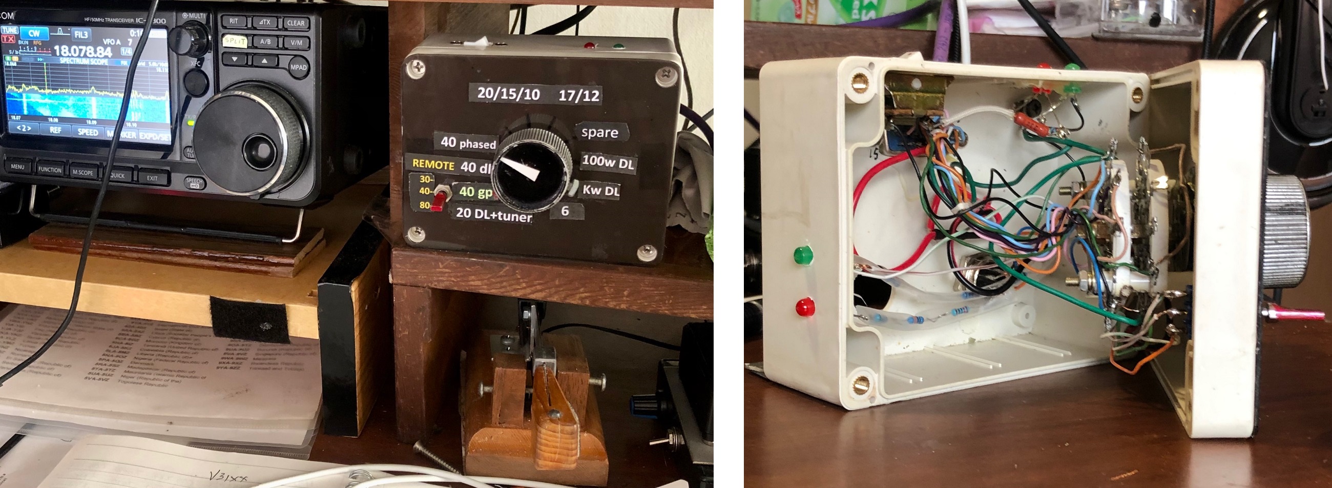
Figure 12. Schematic diagram of the antenna switching system.
I achieved my goals of clearing my desk of cables and making it easy and fast to change antennas. It is not automatic, but I have two hands and do not mind using one to operate the rig and the other to turn the antenna selector. Designing and building the remote antenna switch was an inexpensive and enjoyable project that really improved my operating. If you are tired of the hassle of changing antenna cables, I highly recommend that you add this function to your shack.
73 from chilly Okinawa
From Steve's WorkbenchŃÇÇbacknumber
- Another SOTA antenna, and some thoughts on antenna efficiency
- The Versatile Vertical Delta Loop
- An improved portable Magnetic Loop ÔÇťMagloopÔÇŁ Antenna
- Small wonder: The Evolution of the uSDX and other QRP transceivers
- I learned about relays by rebuilding some Workbench projects
- Cheap but effective satellite antennas ÔÇô Part 2: Directional antennas
- Cheap but effective satellite antennas ÔÇô Part 1: Omnidirectionals
- 18/24 MHz rotatable dipole,ÔÇťRandom-lengthÔÇŁ, end-fed, multiband antenna
- My shack was a jungle of cables! The solution was a remote antenna switching system.
- Remote Antenna Tuners ÔÇô Part 2 ÔÇô Designing, Building, and Testing a Remote Antenna Matching Unit
- Remote Antenna Tuners ÔÇô Part 1 ÔÇô Why Use A Remote Antenna ÔÇťTunerÔÇŁ