


From Steve's Workbench
18/24 MHz rotatable dipole,
“Random-length”, end-fed, multiband antenna
Hams often joke that you can never have too many radios, but my “mania” is antennas. There are nine antennas on my 8 by 12 meter roof, plus four in my portable kit. In this article I describe two more HF antennas I recently built. Next month I will discuss some low-cost but effective VHF/UHF antennas.
An 18/24 MHz rotatable dipole
After replacing my 6-band Hexbeam with a Yagi for 14, 21, and 28 MHz, I put up a parallel dipole to cover the 18 and 24 MHz bands. It worked reasonably well, but it was not very high off the roof so I decided to replace it by a rotatable dipole that I could install above the Yagi. A rotatable dipole is sometimes used when a Yagi is just too big. It will have less forward gain than a Yagi and the same “figure-eight” radiation pattern as a regular dipole, but it can be turned so the main lobes are in the right direction. In my case, it was also a way to get higher elevation.
A common method of making a multiband dipole is with resonant traps. There is plenty of information available for making trapped wire dipoles, but I had read an article about an 18/24 MHz rotatable dipole and immediately set out to build one. I was so excited that I kept the lights on in the workshop until 2 AM and then started work again after a cup of coffee in the morning. But before I describe the build, let’s talk about traps.
A trap antenna uses parallel LC resonant circuits to isolate a section of the antenna by presenting a high impedance on a particular frequency. A two-band trap dipole is shown in Figure 1. The inner sections of the dipole are a half-wavelength near the frequency where the trap is resonant, so a feed impedance of around 70 ohms is presented to the feeder on that band. On the lower frequency band, the traps act as a small inductance, so again a low impedance is present at the feedpoint because the entire length of the antenna is an electrical half-wavelength.
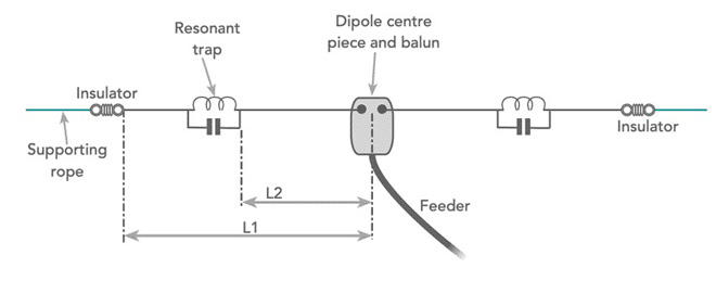
Figure 1. Schematic diagram of a 2-band trap dipole
There is no theoretical limit to the frequencies or the number of bands that can be added by means of more traps and radiating elements. Not only is the band-switching automatic once the antenna is tuned, but for the lowest frequency band, the overall length will be less than an ordinary half-wave dipole because of the net inductance of the traps.
A lot of engineering goes into the design of traps for commercial antennas, but they can be constructed in the home workshop. A coil of wire and a high-voltage capacitor make a simple parallel trap. The resonant frequency of a trap should be slightly below the higher band, and the L and C values should have reactances of around 150 to 250 ohms. Another method of making a resonant trap is to wind a length of coaxial cable onto tubing, as shown in Figure 2. The inductance and capacitance of the coaxial cable itself form the resonant circuit. There are online calculators for the dimensions, but this type of trap is more difficult to adjust to the desired frequency.
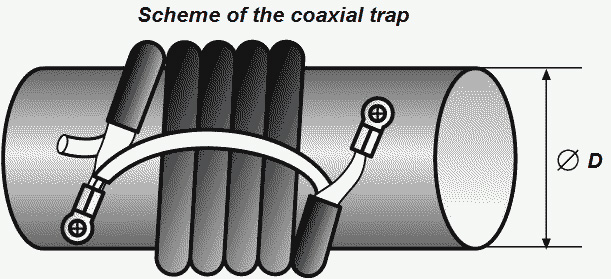
Figure 2. A trap made with coax cable
Since I had never made an antenna like this, I followed an online article, “Build a 12/17 Meter Trap Dipole” by Phil Salas, AD5X. The inductance and capacitance needed for a 24.5 MHz trap were about 1.1 microhenries and 40 picofarads. For the coils, I used 2 mm bare aluminum wire on 1 inch (25.4 mm) diameter fiberglass tubing, but PVC will also work, and I used the same tubing for the dipole center insulator.
Rather than buying high-voltage capacitors, AD5X made his own using 40 mm PVC pipe as the dielectric. I had stainless steel tubing that fit closely inside the PVC, and used aluminum duct tape for the outer capacitor “plate.“ Using an L/C meter, I adjusted each capacitor to 35 picofarads by sliding the inner tube. I used stainless self-tapping and threaded hardware to fasten ring connectors to the capacitor. Figure 3 shows the assembled traps before insulating them. (I changed the connecting leads to solid copper wire.) I adjusted the coil turn spacing for resonance at 24.5 MHz using my nanoVNA, but with open traps like these, an antenna analyzer or grid-dip meter can be coupled to the coil. The exact resonant frequency is less important than getting both traps the same.
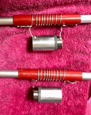
Figure 3. My traps before insulating them
The 240 cm long inner antenna elements are made from 19 mm OD aluminum tubing, joined to the traps with pieces of 16 mm OD tubing by slitting the ends with a hacksaw and using hose clamps (Figure 4).
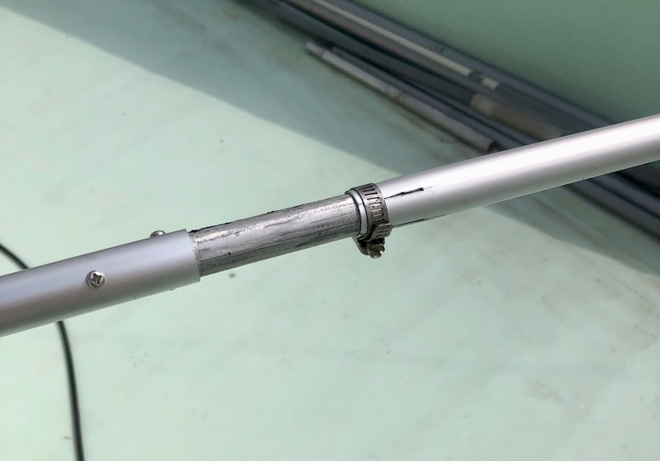
Figure 4. Tubing is joined by slitting and using hose clamps
The 50 cm outer elements are connected to the traps the same way, and the inner and outer lengths can both be adjusted. I connected the traps and elements with self-tapping screws, which make reliable contacts if the screws are of adequate size and tightness. There was a very tough coating on the DIY-store tubing. It will keep the tubing looking new for many years, but it is an insulator and very difficult to remove. Fortunately, the inside of the tubing is not coated. If you find tubing that does not have this coating, by all means use it!
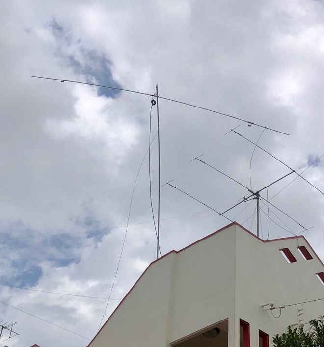
Figure 5. Temporary mounting for testing
I tuned the antenna using an antenna analyzer connected through several meters of coax, after temporarily hanging it as high as possible and away from conductive objects. A choke balun at the feedpoint helped to get stable readings. I first adjusted the inner sections equally to get a VSWR dip at 24.950 MHz. This resonance is fairly broad. Then I adjusted the outer elements for another resonance at 18.100 MHz. Those changed somewhat when I raised the antenna, and they also interacted with each other. I confirmed the adjustments at the shack end of a 23 meter length of RG-213, as seen in Figure 6.
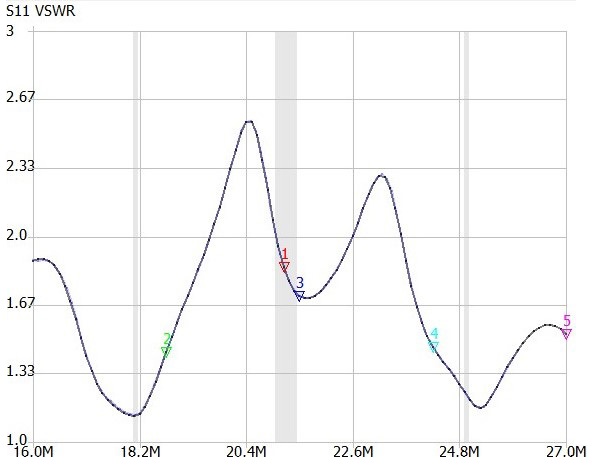
Figure 6. VSWRs at the end of the 25 meter long feedline
I have not yet put the rotatable dipole on the Yagi mast, which will make it about 8 meters higher, but from the excellent signal reports so far the radiated pattern of the new dipole is better than the old one, which had conductive supports close to its high-impedance ends. In my experience, 18 and 24 MHz are difficult bands to use in a single antenna, but now I think I can tackle any multiband trap antenna, even multi-element Yagis since the parasitic elements are similar to the dipole.
A “random-length” end-fed, multiband antenna
My other recent project is an addition to my SOTA antenna arsenal. I had high hopes for the portable magloop antenna I described in FB NEWS several months ago. It worked well on initial outings, especially on the bands where its efficiency is high. Its advantage for SOTA is the small footprint (only one support pole) and light weight, but on a windy summit it was hard to keep it from blowing over and tuned accurately.
Why don’t I just rely on my well-tested “Chairtenna” vertical ground plane, (see my October 2021 article), which performs well on four bands, and provides a comfortable operating position? Or the triband wire dipole that worked so well from my hotel balcony on a DXpedition? In fact, the Chairtenna pack is bulky and a bit heavy, and it needs two people to set up if it is windy. The dipole is lightweight and small, but requires two high mounting points, and neither covers all the bands that I can now use with my new uSDR QRP rig (Figure 7).
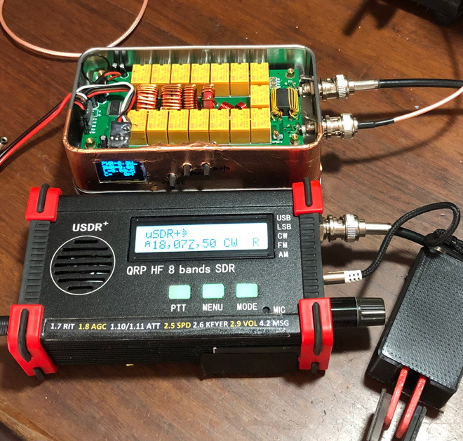
Figure 7. My new uSDR+ radio and AT-100 matching unit
I was not a great fan of end-fed wire antennas, but many hams are, especially the resonant end-fed halfwave (EFHW). They are now mega-popular because they work on harmonically related bands, are easily installed, cheap, and get good results. The principle is that a half-wavelength antenna can be fed at any point, at the center where the impedance is low, to an end where the impedance may be as high as 3,000 ohms. Feeding it at the end makes for a simple installation, only requiring impedance transformation down to 50 ohms. It also needs a counterpoise, but needs no additional matching device if it is adjusted correctly.
There is nothing special about an antenna that is resonant, but some amateurs incorrectly equate non-resonant with inefficient. Any conductor radiates if RF current flows through it, resonant or not. Of course, the geometry and dimensions of the antenna, its height above ground, and so on, determine the effectiveness of antennas. But if we just compare simple wire antennas, practical factors may decide which is “best”, such as ease of installation and matching, common-mode currents, and cost. The EFHW has some real advantages, especially for fixed installations where it can be adjusted properly and left in place, but in my opinion the random-length end-fed has even more.
The “random-length” end-fed wire at first seems similar to the EFHW, but technically is rather different. A wire antenna that is not resonant will have a feed impedance between the extremes found on a resonant wire, roughly 200-1200 ohms. A 9:1 stepdown “unun” (unbalanced-to-unbalanced transformer) reduces this range to 22-130 ohms, which can be easily matched to the rig by internal or external antenna tuners.
It is not really a random length antenna though, because a length of wire that has the right range of impedances in the bands of interest must be used. An excellent explanation with many examples is in a video (www.youtube.com/watch?v=4lzlZxxUzM0) from Palomar Engineering in the USA, which provides solid information on antennas they sell. They also sell the 9:1 unun, but those are very easy to make (Figure 8). For the HF bands, the ferrite core used is usually iron powder type -2 or -6 of a size appropriate for the power level, and the construction is not critical.
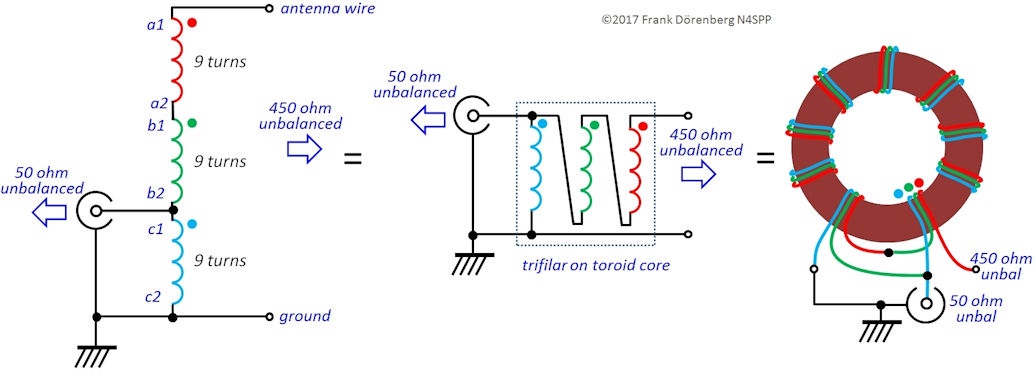
Figure 8. Schematic diagram of a 9:1 unun
For the new builder, the difference between the two antennas is also oddly psychological. To build an EFHW, you get a 49:1 unun and hang up a specific length of wire, usually a half-wavelength on 3.5 or 7 MHz. A counterpoise of a specific length is also needed. In contrast, a random end-fed antenna must be a length that is not a half-wavelength on any band. A new builder looks at charts and tables such as Figure 9 and wonders how to choose the best length. Avoiding the resonant “forbidden” lengths is easy, but do all the remaining lengths work equally well?

In my experience, they do not, so some trial and error may be required, starting with a wire that is at least a quarter-wavelength on the lowest band you want to operate on. There is also the matter of the counterpoise or coax cable length. The advice ranges from very specific lengths, to "does not matter," and the way the wire is deployed also has a relatively small effect compared to the length. I first tried the shortest suggested lengths (8.8 and 10.7 meters), but I could not get a good match on some bands. I went up to the next recommended length (12.5 meters), and this gave a good match on all bands with the tuner.
Almost any configuration can work if the main part of the wire is high. Figure 10 shows how I have used the antenna in the field. (It took longer to draw the picture than to actually set up the antenna.) The feedpoint at the 9:1 unun is fairly low, with 3 meters of coax laying on the ground connecting it to the transceiver and ATU. A short ground wire to a tent stake also anchors the elevated wire. The inverted-V configuration uses a fishing pole at the midpoint and slopes down to a shorter pole. A choke balun at the autotuner output helps it to tune on some bands.
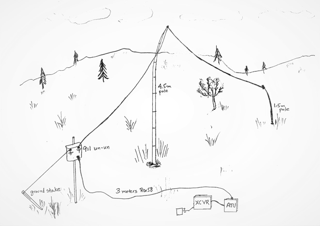
Figure 10. Field installation as an inverted V
I emphasize that the random-wire end-fed is not a new or radical antenna design. On the contrary, it is one of the oldest and best-proven amateur antennas for both portable and fixed use. With the autotuner, I have instant band switching but much less weight to carry and set up than with the Chairtenna. It is not as clever as my folding magloop, but it is also not super-sensitive to tune. So far, the results on the air have been excellent. The random-length end-fed just might become my favorite SOTA antenna.
From Steve's Workbench„ÄÄbacknumber
- Another SOTA antenna, and some thoughts on antenna efficiency
- The Versatile Vertical Delta Loop
- An improved portable Magnetic Loop “Magloop” Antenna
- Small wonder: The Evolution of the uSDX and other QRP transceivers
- I learned about relays by rebuilding some Workbench projects
- Cheap but effective satellite antennas – Part 2: Directional antennas
- Cheap but effective satellite antennas – Part 1: Omnidirectionals
- 18/24 MHz rotatable dipole,“Random-length”, end-fed, multiband antenna
- My shack was a jungle of cables! The solution was a remote antenna switching system.
- Remote Antenna Tuners – Part 2 – Designing, Building, and Testing a Remote Antenna Matching Unit
- Remote Antenna Tuners – Part 1 – Why Use A Remote Antenna “Tuner”