


From Steve's Workbench
Remote Antenna Tuners
Part 1 – Why Use A Remote Antenna “Tuner”
I started working on this project in midsummer, and now as Autumn is fading away, it is almost finished. In Part 1 of this article, I review some theory about antenna matching and the advantage of using a remote ATU. In Part 2 I will cover the design decisions I made in building my own remote ATU and the details of the construction. Thank you for following this project!
If you operate on the high frequency (HF) amateur bands, you might have an antenna tuner built into your transceiver, or an external unit on your desk connected to it. These are more correctly called Antenna Matching Units. Why do I make this clarification, and why are they so popular regardless of what they are called?
On the left side of the photo below, an inexpensive automatic mini-ATU rests on a vintage manual tuner, while to the right is a much-modified $15 “eBay” portable tuner and an automatic MFJ-993B ATU. Though these all look different, they have the same function; they match the impedance of a “load”, such as an antenna, to the impedance of a “source”, such as a transmitter. A review of impedance matching will help explain why ATUs are used.
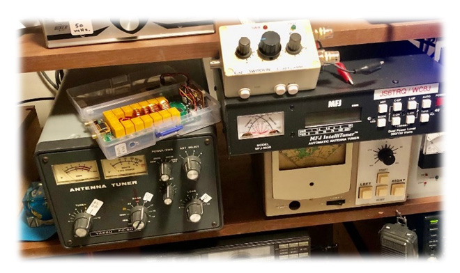
Some antenna matching units in my shack
AC Circuits
All electrical circuits are a combination of resistance (R), inductance (L), and capacitance (C), that resists (impedes) the flow of current when alternating (AC) voltage is applied. Resistors behave just as they do in a DC circuit, but the inductors and capacitors have the property called reactance. The resistor dissipates power just as for DC, but reactance only shifts the phase of the AC current relative to the voltage and does not consume any power.
I will get around to ATUs and antennas soon but let us look at a circuit that you might build on your workbench (Figure 1). The resistance does not vary with the frequency of the AC source, but the reactance depends entirely on frequency. Inductive reactance increases with frequency, while capacitive reactance decreases with frequency, and the phase shift also depends on the frequency because the inductance and capacitance shift it in the opposite directions. On the graph, R is on the horizontal axis and XL and XC are on the vertical axis. Unless the two are equal, there will be some net reactance on the vertical axis. Resistance and net reactance form a right triangle; the impedance Z is the length of the hypotenuse, and the angle it makes with the horizontal axis is the phase shift in the circuit. You can see that if the net reactance is zero, there is no phase shift, while if there is zero resistance, a pure inductance causes a +90 degrees phase shift, or -90 degrees for a pure capacitance.
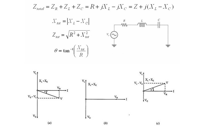
Figure 1. Properties of a series RLC circuit.
We denote reactance as “imaginary” numbers, +jX or – jX, so the impedance formula is often written Z=R+jX (“j” is the same mysterious i= √-1 that you met in junior high school). If XL and XC are equal, they cancel out, and there is zero phase shift. This occurs at the resonant frequency, and the inductive reactance and capacitive reactance are then called conjugates.
All radio communication is based on sending AC energy through a transmission line and into a circuit that has the special property of radiating some of that energy into free space, which we know as the antenna. In a good antenna, most of the resistive part is the radiation resistance in free space and depends on the type of antenna. Many people know that a half-wavelength, center-fed dipole has radiation resistance of about 70 ohms at its resonant frequency. At other frequencies, and even at the resonant frequency, antennas will also have some reactance.
But regardless of the type of antenna and the frequency, the only way that an antenna can be tuned is by adjusting the properties of the antenna itself. Most hams have lengthened or shortened a wire dipole in order to get low VSWR (standing wave ratio) at a chosen frequency. The black box in the shack does not “tune” the antenna!
So, what does it actually do? The answer is that it is an impedance matching device that converts the impedance of the antenna system to the impedance required to get maximum power from the transmitter. In Figure 2a a 50-ohm transmitter is connected to the left-hand terminal, and the feedline from the antenna is connected to the opposite terminal. The network can consist of one or more reactive components (Figure 2b). Figure 2c shows possible matching network “topologies”. The principle of simple transformers shown at the bottom is very familiar, but most ATUs rely on “L,” “T,” or “pi” networks for impedance matching. All of the topologies can match a wide range of impedances, and the choice depends on the particular matching needs and available components. Fully automatic matching units use only the two underlined “L” topologies in Figure 2b. I will discuss L-networks in detail in the second part of this article.
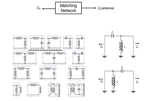
Figure 2. (Top:2a, left: 2b, right: 2c) Antenna impedance matching networks
Let us go back to real life ham radio stations, where you probably have installed four important pieces:
1. Transceiver
It is sometimes said a 50-ohm load attached to the rig “keeps the final amplifiers happy”, but in fact most modern transceivers have circuits that instantly reduce the output power to avoid damage, even if the antenna is accidentally removed (thank you, IC-7300!). There is a more general reason for matching the load impedance to the source impedance, which is that the maximum power is transferred when the impedances are equal. This is a basic fact of electronics and applies from “DC to daylight.”
Let us look at the simple DC circuit in Figure 3 to illustrate this. The voltage source VS has an internal resistance of RS. This might be an ordinary AAA battery or an (unregulated) DC power supply. Assume that the open circuit voltage VS is 20 volts, and the internal resistance is 100 ohms. A load resistance RL is attached, making the circuit a voltage divider. RL can be any resistance we choose, but we want this resistor to get as hot as possible, so we try several resistances. If we calculate the power dissipated by the load resistor (W=E2/R or W=I2R), we find that a resistor of the same value as the source resistance,100 ohms, takes more power than any other value (Figure 4). Simple calculus can prove that maximum power is always transferred when the source and load resistances are equal. The greater the mismatch, the less power is transferred to the load.
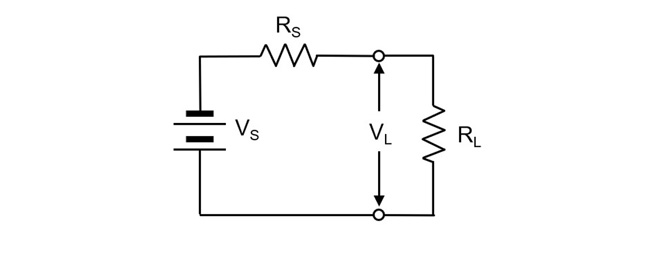
Figure 3. A simple voltage divider with a source having internal resistance
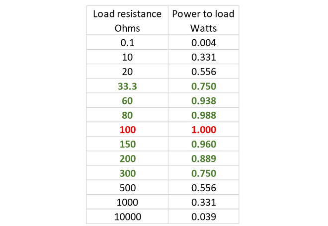
Figure 4. DC power transferred to different resistances.
For an AC source like a radio transmitter, the same rules apply as for DC. The difference is that in order to transfer maximum power from a source to a load with complex impedance ZL=RL+jXL, the source must have the equal but opposite reactance ZS=RL-jXL. Modern transceivers are designed so the final amplifiers have a source impedance of approximately 50 ohms at full power. If a much higher or lower impedance is connected, the output will be less than full power, and this can be seen on an output power meter.
2. Antenna System
Your antenna system has a certain impedance (Z) at any given frequency. It might be high or low, and it might have a reactive part or not. The best way to know the antenna input impedance is to measure it directly. Some antenna analyzers can do this, and the NanoVNA network analyzer is very popular because of its capability and low cost. Measuring the antenna at the feed point is usually inconvenient, but a feedline that is exactly one or more electrical half-wavelengths at a given frequency will send nearly the same impedance to the measurement device, at that frequency.
If the antenna is still only on paper, or in your imagination, you can use modeling software to design it. These programs (EZ-NEC and MMANA-GAL are popular ones) allow you to draw the antenna, or modify many existing designs, and then calculate a variety of results such as the radiation pattern, the bandwidth, the current distributions, and specifically, the input impedance. You can make the calculation on any frequency, not just for the band(s) you plan to use it on.
3. Transmission line
The transmission line (feedline) sends power from the transmitter to the antenna, and this transmission line itself has a characteristic impedance that does not change with frequency. Coaxial cable with a characteristic impedance of 50 ohms is the most popular transmission line now used by hams. The transmission line will reflect the antenna impedance down to the transmitter under certain conditions, primarily that the impedance is only resistive, and is the same as the characteristic impedance of the transmission line. The antenna is then matched to the transmission line. The voltage standing wave ratio (VSWR) is the ratio of the highest to the lowest voltage or current along the line. VSWR changes with frequency because the antenna impedance changes. I used the modeling program MMANA-GAL to demonstrate this for the popular Inverted-Vee dipole for the 7-MHz band. The table below shows low calculated impedance and VSWR on 7-MHz and 21-MHz bands as we expect, but very high values on the other HF bands.
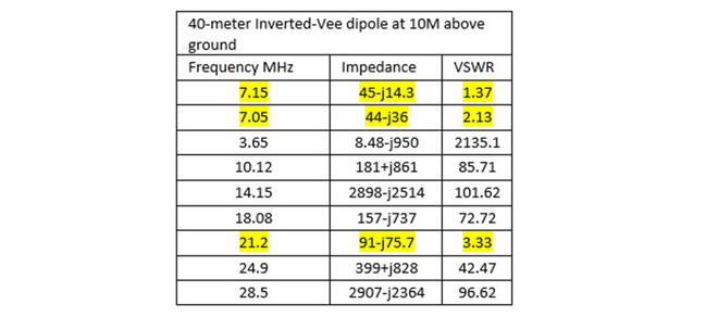
Figure 5. Calculated input impedance of a 7-MHz Inv-V antenna on HF bands
All feedlines lose some RF power on the way to the antenna. Generally, smaller coaxial cables have higher losses than larger ones, with loss increasing as frequency increases, and as the VSWR increases. Some have lower losses, including “ladder line” and expensive cables such as Heliax. The losses are due to the resistance of the conductors, the loss in the dielectric, and the “reflected” loss, power that cannot be transferred to the antenna because of impedance mismatch. I keep a very useful calculator for transmission lines called TLDetails bookmarked on my PCs. It quickly calculates the loss and impedance transformation for most kinds of lines, for any frequency and length. Please play around with TLDetails, and you might want it on your desktop too.
4. ATU
Some transceivers have an internal automatic antenna tuner (ATU) that allows a load other than 50 ohms to be attached to the radio without any output power reduction. These internal tuners can usually only compensate for a fairly small maximum VSWR like 3:1. External tuners are used if there is no internal ATU or when a wider range of impedances must be matched, such as with “compromise” antennas like the G5RV or end fed wires that many hams with restricted space must use. The VSWR in the feedline between the ATU and the transmitter is easily adjusted to be very low. Even ATUs that can handle a lot of power and run completely automatically are fairly inexpensive nowadays and can include antenna switches. These facts explain why external tuners are probably the most popular HF shack accessory.
Referring back to Figure 2, most automatic antenna matching units use the “L” network topology to match impedances over a wide frequency range, using up to ten different sizes of L and C that can be switched in parallel to make almost any required total value. They use logic circuitry and algorithms to quickly produce a configuration that matches the impedances, and some also have frequency measuring and memory capabilities. In contrast, most manual tuners use “T” and “pi” topologies with large variable capacitors and inductors. These also have a wide frequency and impedance range and can handle high power. If you have time for some desktop fun, please download “T-network Tuner Simulator” and design your own ATU. I used it when I modified my cheap “eBay” QRP tuner. If you are also interested in seeing an automatic tuner at work on your PC, download “L-Tuner Simulator 1.2”

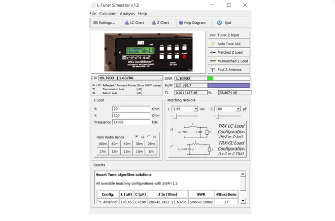
Figure 6. Antenna matching simulators
(Top: Manual T-network, bottom: Automatic L-network ATU)
Can these relatively inexpensive devices make an antenna work better? Yes, but not always. Apart from minor power loss in the network, the main drawback is that, even if the VSWR between the radio and the tuner is low, the VSWR between the ATU and the antenna can still be high. This is not always very important, and problems caused by high VSWR in the shack can usually be cured. Nevertheless, long feedlines and high SWR can cause high losses, especially on the higher bands. TLDetails can help us understand what could happen with our antenna system. Using the Inv-V from the above example, and a relatively short (20 meters) RG-58/U feedline, the calculated power loss is shown in Figure 7.
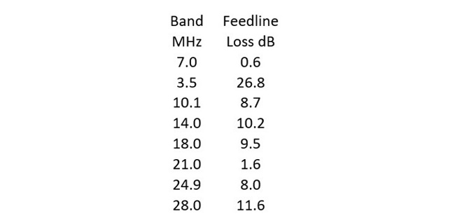
Figure 7. RF power loss in 20 meters of RG-58/U cable with a 7-MHz Inv-V
We cannot expect low losses on all bands, but some of these are really ugly! The Inverted-Vee dipole is sometimes the only HF antenna possible and could be a good radiator on most bands. For example, on the 3.5-MHz band, it would have quite a useful radiation pattern, but the feedline losses are equal to more than four S-units. On 28-MHz, the 11.6 dB loss means that 100 watts into the feedline results in only 7 watts at the antenna.
The Remote Tuner Solution
If the impedance matching unit is moved from the operating desk and placed close to the antenna, the VSWR on even a long transmission line to the transmitter can be made very low, and feedline losses nearly eliminated. Comparison of the layouts is seen in Figure 8.
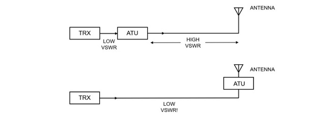
Figure 8. Antenna Matching Units in the shack and at the antenna
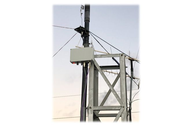
Remote matching units became practical when automatic tuning technology was perfected, but they are considerably more expensive than desktop models because they must be rugged and weatherproof. Units that can handle 100 to 300 watts cost around US$300, while models that can handle high power cost from US$900 to US$1400. I wanted one for medium high power, but to match only one antenna on two different bands. I had many vintage parts in my junk box, so I decided to build my own remote tuner, but without any elaborate digital controls. The box attached to the tower is what it looks like installed.
In the final installment I will discuss the design and construction of this remote antenna matching unit. 73 until next month!
From Steve's Workbench„ÄÄbacknumber
- Another SOTA antenna, and some thoughts on antenna efficiency
- The Versatile Vertical Delta Loop
- An improved portable Magnetic Loop “Magloop” Antenna
- Small wonder: The Evolution of the uSDX and other QRP transceivers
- I learned about relays by rebuilding some Workbench projects
- Cheap but effective satellite antennas – Part 2: Directional antennas
- Cheap but effective satellite antennas – Part 1: Omnidirectionals
- 18/24 MHz rotatable dipole,“Random-length”, end-fed, multiband antenna
- My shack was a jungle of cables! The solution was a remote antenna switching system.
- Remote Antenna Tuners – Part 2 – Designing, Building, and Testing a Remote Antenna Matching Unit
- Remote Antenna Tuners – Part 1 – Why Use A Remote Antenna “Tuner”