


From Steve's Workbench
An improved portable Magnetic Loop “Magloop” Antenna
Magnetic Loop Antennas or Magloops (also called Small Transmitting Loops) have been popular with radio amateurs since the 1960s, used mainly at fixed stations where space for HF antennas is restricted. Although they have drawbacks, they are very compact and work surprisingly well at almost any height, and even indoors.
High power Magloops use heavy and expensive components such as vacuum capacitors and automatic motor drives, but recently manufacturers have introduced Magloops for low power and portable use. Outdoor operation and friendly competitions such as Parks on the Air (POTA) and Summits on the Air (SOTA) have become very popular. Radio gear is carried to the site and set up in sometimes difficult conditions. Simple wire or whip antennas are most used, but Magloops could be useful if they are effective and lightweight. The one described in this article is not elegant in construction but it works very well on HF bands. It weighs only 2 kgs including a tripod and can be set up quickly.
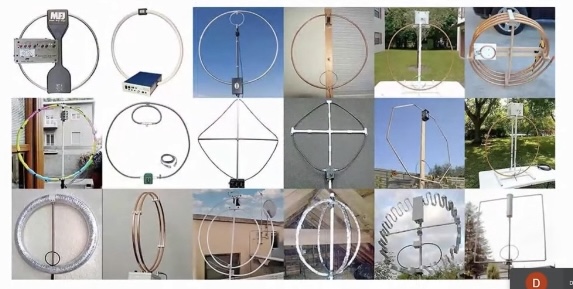
Fig. 1. Some experimental and commercial Magloops. Commercial antennas cost hundreds of dollars but one can be built for much less.
A Magloop is basically a large inductor that is tuned to a specific frequency by a capacitance. The resonant circuit radiates an electromagnetic field because of high circulating voltage and current. For receiving, the high Q loop produces relatively high voltage from incoming signals, and its selectivity and directionality help reduce interference. It is claimed that this type of antenna does not pick up as much noise as conventional antennas because it responds mainly to the magnetic component of radio waves, but this is probably not the actual reason.
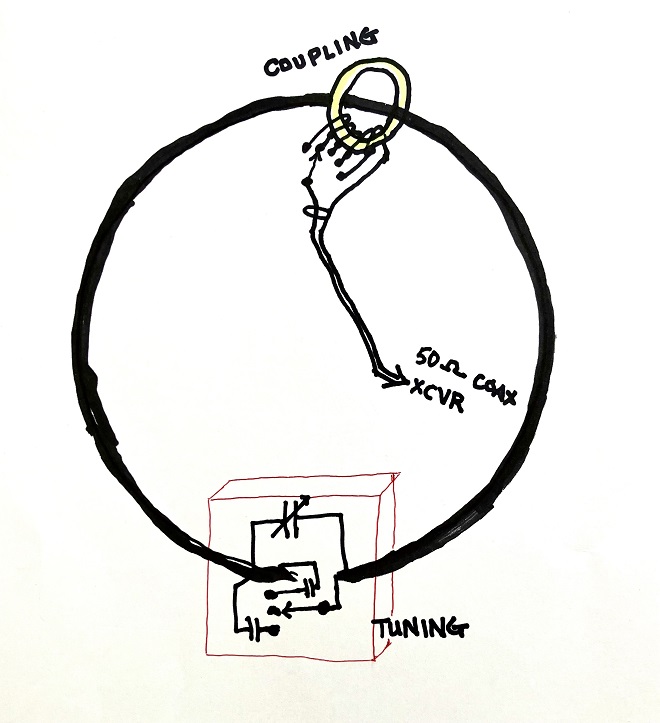
Fig. 2. The critical parts of the portable Magloop.
The main loop is the most important part of the antenna. It can be made from copper or aluminum tubing or from coaxial cable, or even from a hula hoop or an aluminum bicycle rim. The resistance of the loop must be extremely low and its circumference about 1/10 of a wavelength at the operating frequency. Online calculators can find the best size for a given band, the capacitance needed for resonance, and the resulting efficiency, bandwidth, current and voltage. The Small Transmitting Loop Antenna Calculator (https://www.66pacific.com/calculators/small-transmitting-loop-antenna-calculator.aspx) is an easy one to use, but they all can provide a starting point for experimentation.
I had built single-band Magloops for 7 and 18 MHz but was not happy with their performance. Now I wanted a multi-band Magloop, which would be even more of a challenge to work well. A compromise size loop can work on several bands, although not with equal efficiency. For example, the calculator indicated that a loop of 4-meter circumference would cover 7 through 24 MHz, but the size was not ideal for the highest and lowest bands. A test loop could only reach 20.5 MHz because of stray capacitance, so I had to make it smaller.
The theoretical efficiency of this loop (relative to a dipole antenna) is shown below. On the lower bands one or two S-units are lost, but the higher bands are quite good. These calculated efficiencies are for an ideal loop with zero resistance so a real loop will be less efficient, but hopefully not by too much.
7 MHz 21% efficient, or -6.8 dB
10 MHz 48% efficient, or -3.2 dB
14 MHz 75% efficient, or -1.2 dB
18 MHz 88% efficient, or -0.6 dB
21 MHz 93% efficient, or -0.3 dB
24.9 MHz 96% efficient, or -0.2 dB
My first multi-band portable Magloop used four 1-meter lengths of rectangular aluminum with folding joints designed to have low resistance. Performance was good, but it was awkward to carry and difficult to set up and use because of wind resistance.
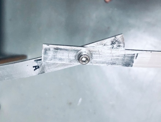
Fig. 3. Detail of my first portable Magloop.
High pressure is applied to large surface area joints for low resistance.
The next loop version was made from low-loss 5D-FB coax cable. This one was easy to fold for carrying, easy to set up, and performed well on the air. It included a small motor so it could be tuned from several meters away.
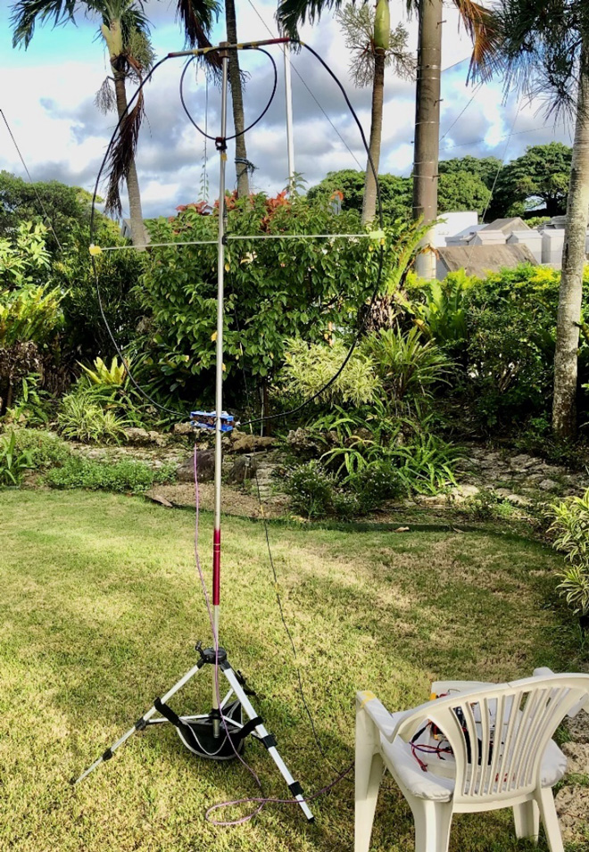
Fig. 4. The second version was remotely adjusted and used a small loop to couple the feedline.
A video called “In Search of the Optimized Transmitting Magnetic Loop,” showed that antenna efficiency is greatly improved by using larger diameter conductors, and this is also indicated by online calculators. The video includes novel low-cost construction techniques to make efficient Magloops
(https://www.youtube.com/watch?v=mDL6dea_aZk).
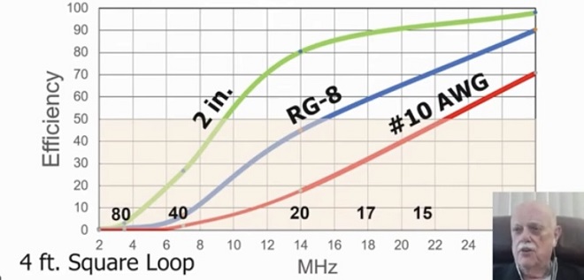
Fig. 5. Magloop efficiency increases with the conductor size, from a video by W6NBC
A large-diameter loop conductor can be light, efficient, and made of inexpensive materials because of the skin effect, where RF currents flow only in a thin region near the surface of a conductor. The RG-8 and similar cable used in commercial Magloops makes a nice portable package, but is not as lightweight or as efficient as possible. I wanted a large diameter but flexible material that could maintain a loop shape, but was also light weight and very low resistance.
I considered using semi-rigid aluminum ducting, but it is very bulky and would have high wind resistance. Another type of flexible ducting made with metallized plastic foil can collapse like a Slinky toy for easy carrying, but it worked poorly in a test model because of its high electrical resistance.
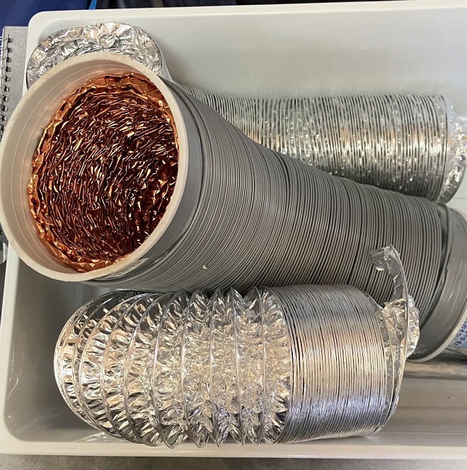
Fig. 6. Foil-lined collapsible duct materials had high resistance.
I looked closely at the FB-series coaxial cables, which are low loss and light weight and use a thick solid center conductor, foam dielectric, inner foil shield and outer copper braid. I found that most of the weight is in the center conductor, dielectric, and plastic jacket. The remaining copper braid can be separated easily and is an excellent conductor, but cannot hold a loop shape by itself.

Fig. 7. Chinese Finger Trap was the inspiration for expanding the coax braid
I separated a seven meter length of the 5 mm braid from 5D-FB cable and pushed it over four meters of 10 mm vinyl tubing, making a hybrid 11 mm diameter conductor that was stiff and lightweight. It could be folded easily, held a loop shape when supported, and worked well when I tested it on the air. The braid from 10D-FB cable could expand to 20 mm, but that size vinyl tubing is quite heavy. The conductor that I use now is a compromise, using braid from 8D-FB cable expanded onto thin 16 mm vinyl tubing.
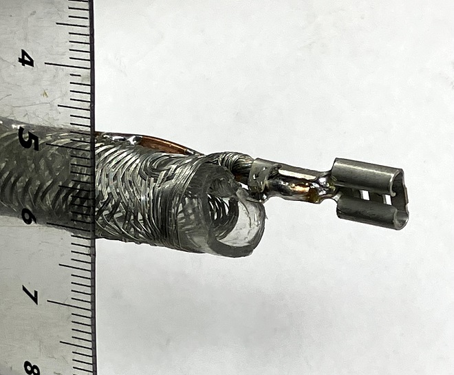
Fig. 8. Copper braid from 5D-FB coax expands onto 10-mm vinyl tubing. Automotive-type connectors are soldered to the braid.
The tuning capacitor should not add resistance to a Magloop, but good small variable capacitors are now hard to find. I first used one that had 0.5 mm plate spacing and a range of 10 to 50 picofarads. It resonated the loop from 12 to 25 MHz, and down to 7 MHz by adding fixed capacitors in parallel. I did not pay attention to the calculation that five watts of power would put 700 volts on the capacitor, and it arced over one humid evening. I replaced it with one having 1.0 mm spacing and the same capacitance range which is heavier but can handle 50 watts. A 500-volt mica capacitor also burned up, so I added another in series for higher voltage capability.
The circulating current is also very high, as much as 4 amperes from 5 watts. I reduced resistance with copper strips bolted to the variable capacitor and used automotive type electrical connectors to connect to the loop. These are intended for high current, can be connected quickly, and are light and cheap.
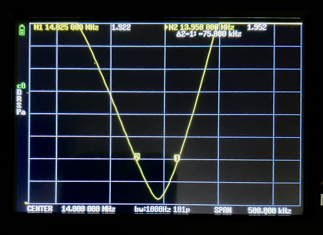
Fig. 9. The VSWR curve indicates high Q, but the small remaining resistance makes the bandwidth wider than an ideal Magloop.
The bandwidths measured at the 2:1 VSWR points are approximately twice that calculated for an ideal loop. This does not seem to degrade the performance, and makes direct tuning quick and easy with a reduction drive. The calibrated dial has useful preset marks, and the entire tuning module is shielded with copper foil to reduce the effect of hand capacitance.
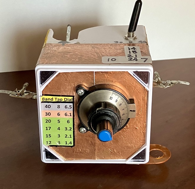
Fig. 10. Tuning capacitor module with toggle switch for fixed capacitors.
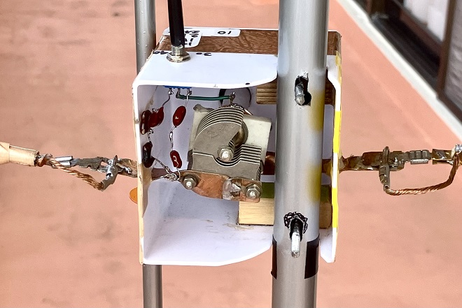
Fig. 11. Low-resistance connections to the variable and fixed capacitors.
Matching a high impedance loop to the feedline is most often done with a small coupling loop. It is easy to make and works well, but can require the shape and position to be changed for different bands. The Gamma match is compact and needs little adjustment but slightly distorts the antenna radiation pattern. I have had the best results by running the loop through a ferrite toroid core with several turns of wire on it connected to the feedline. The size of the toroid and its position on the loop are not critical, but the number of turns depends on the band in use. In my final version, taps on the coil are selected by a rotary switch, from two turns on the highest bands to eight turns on 7 MHz. This gives very low VSWR on all bands, making the complexity worth the trouble.
In fixed and high power Magloops, the tuning capacitor (with motor) is usually mounted at the top so the high impedance point is far above ground and the feedline is not in the field of the loop. That would make a portable Magloop top-heavy and difficult to tune, so the capacitor is usually placed at the bottom of the loop near the operating position. This is more stable and causes no problems at low power.
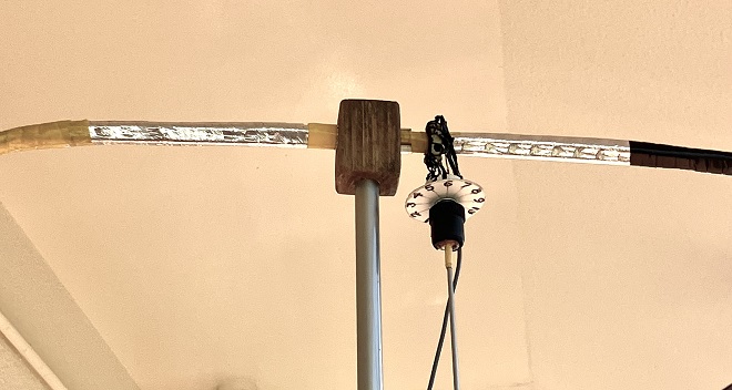
Fig. 12. The toroid and selector switch fit snugly on the loop, which can be quickly attached to the vertical support. Leftover shield foil from the coax protects the braid.
Having improved the antenna efficiency and reduced its weight, I also wanted the supporting structure to be light and easy to set up. Wood or PVC conduit can be used for the support frame, but fiberglass telescoping fishing poles are lighter, compact, and more rigid. (Carbon-fiber is unsuitable because of its conductivity.) I use the thicker lower sections to bear weight, with holes drilled to hold other parts.
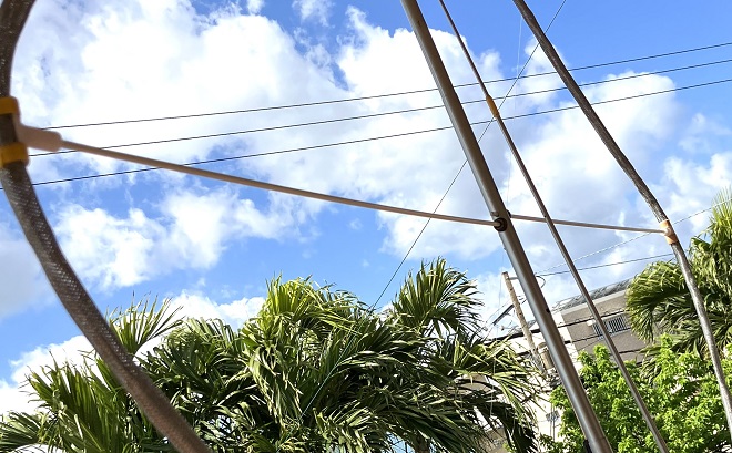
Fig. 13. The loop is supported by a telescoping fishing pole and horizontal fiberglass rods. The extension rod for the rotary switch is made from the thinnest pole sections.
The first step when setting up the Magloop is to fasten the center of the conductor to the top of the pole with a cross-drilled block. The cross supports are thin fiberglass garden stakes that fit in holes in the vertical pole, with T-shaped pieces on the outer ends that hold the loop in place.
Previously, to erect the antenna I hammered a metal stake into the ground and placed the bottom end of the pole on it, but it would fall over in the wind if the ground was too hard or soft. I modified a lightweight camera tripod to spread the legs wider, locating the bottom of the loop around one and a half diameters above ground level, which is considered an effective height. A pouch attached to the tripod legs can be weighted with stones or sand from the site for greater stability.
With the feedline connected to the toroid switch, I extend the telescoping pole and mount it on the tripod. The tuning module attaches to the pole and connecting it to the loop ends keeps the cross supports in place. This completes a very stable loop that takes only two minutes to set up.
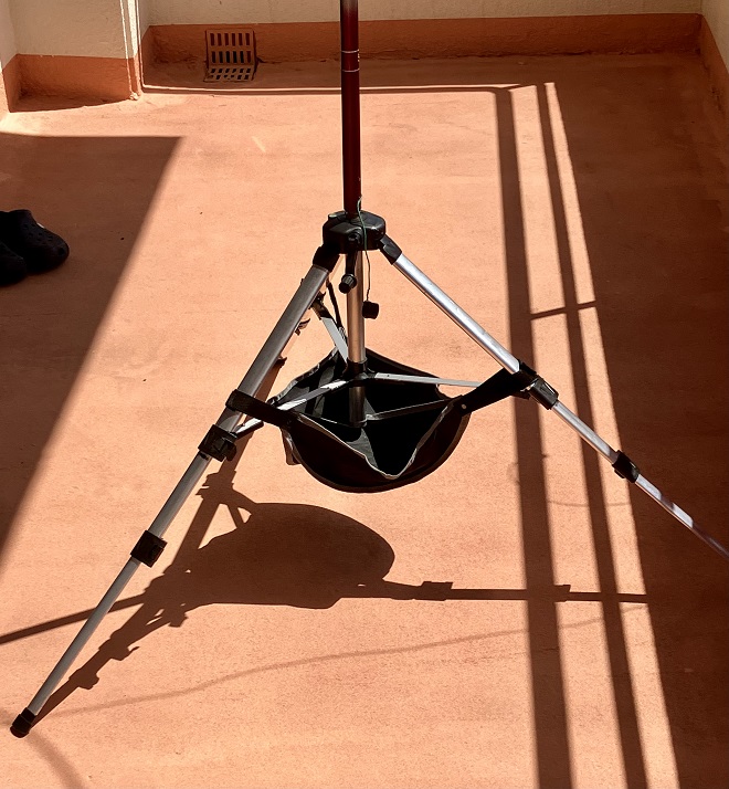
Fig. 14. Modified tripod and the pouch for adding temporary weights.
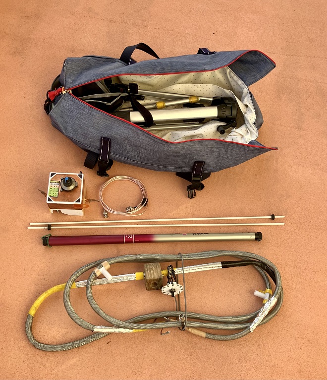
Fig. 15. The tripod and Magloop parts fit in a custom bag, made by Mrs JS6TMW
With the Magloop assembled and a transceiver connected, I preset the tuning capacitor and toroid switch for the operating band. Daytime propagation on 7 MHz from Okinawa is usually poor so I start on 10 MHz, followed by the higher bands. An increase in background noise can be heard by tuning the capacitor around the preset mark. No other antenna tuner is needed. I send a carrier or some dits and slowly tune the capacitor for a sharp dip in VSWR. The ability to change bands quickly is a big advantage in SOTA operation, and even QRP brings DX contacts on the higher bands. Rotating the loop can increase the strength of received signals or null out interfering ones. During the recent JA SOTA Party I made instant comparisons with a full-sized vertical antenna. Reports with the Magloop were within one S-unit of the vertical, and the noise floor was considerably lower.
In summary, I am very satisfied with the portable Magloop. If you decide to build your own, you can find a thorough discussion of the theory of Magloops and many practical details in the video I mentioned earlier and at https://www.nonstopsystems.com/radio/frank_radio_antenna_magloop.htm.
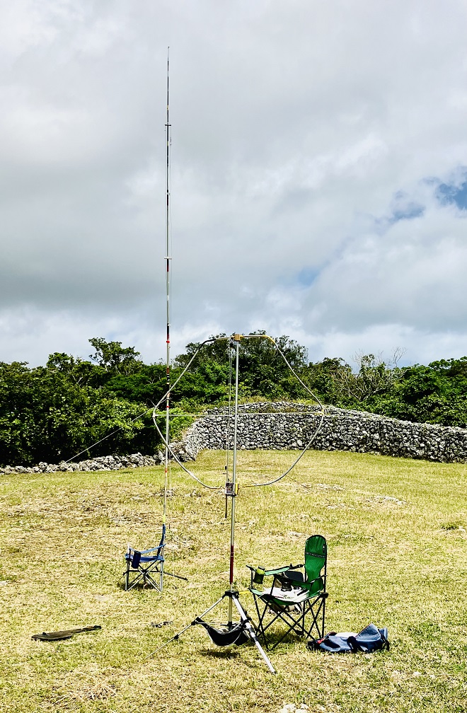
Fig. 16. The Magloop compared favorably with a much larger vertical antenna with radials.
(Credits)
Fig. 1: from W6NBC
Fig. 3: from Japan Castles on the Air, October 2021 FB-NEWS
Fig. 5: from W6NBC
Fig. 7: https://youtu.be/sOLXVQZYwao
From Steve's Workbench backnumber
- Another SOTA antenna, and some thoughts on antenna efficiency
- The Versatile Vertical Delta Loop
- An improved portable Magnetic Loop “Magloop” Antenna
- Small wonder: The Evolution of the uSDX and other QRP transceivers
- I learned about relays by rebuilding some Workbench projects
- Cheap but effective satellite antennas – Part 2: Directional antennas
- Cheap but effective satellite antennas – Part 1: Omnidirectionals
- 18/24 MHz rotatable dipole,“Random-length”, end-fed, multiband antenna
- My shack was a jungle of cables! The solution was a remote antenna switching system.
- Remote Antenna Tuners – Part 2 – Designing, Building, and Testing a Remote Antenna Matching Unit
- Remote Antenna Tuners – Part 1 – Why Use A Remote Antenna “Tuner”