


From Steve's Workbench
The Versatile Vertical Delta Loop
Typhoon Khanun in July was a wake-up call. I had underestimated the strength of the winds and only partially lowered the antennas on my roof. Only a 50MHz Yagi survived the five-day typhoon. I repaired and sold the triband Yagi and patched up the 18/24MHz rotary dipole and the 7MHz vertical ground plane (VGP). I put up a temporary sloping dipole and found I could still work DX stations. No more tower climbing! From now on, I just want one all-band antenna that is easy to lower and raise by rope and pulley. I’ll keep the other antennas as backups for as long as they last.
It is a common misconception that only a resonant antenna can be an efficient radiator, but almost any conductor at least 3/8 wavelength will radiate and can also be used on higher bands. Impedance matching is a different matter, and is important because modern transceivers are designed to use 50-ohm antennas, and because of possible high loss in mismatched feedline. Simple half-wave dipoles or inverted-V antennas fed with coaxial cable work well, but only on one or two bands because the impedances on other bands result in high VSWRs. This problem can be overcome by well-known methods such as resonant traps, parallel elements, off-center feedpoints, and matching lines, with similar methods used for short vertical antennas. An alternative to reduce feedline losses is to use a remote antenna matching unit, but another, sometimes overlooked approach is using open-wire balanced feedline that has very low loss. An online calculator like TLDetails (www.ac6la.com) can easily show the advantage of balanced line over even the best coaxial cables. An antenna tuner is usually used to transform the high line impedance to match the transceiver.
One of the oldest multi-band antennas is a simple dipole (doublet or Zepp) fed with balanced line (Figure 1). The horizontal wire does not have to be a resonant length, so the VSWR may be high but this does not matter because the loss will be low. Parallel feedlines used by amateurs include 300-ohm “twinlead”, the wider 400-ohm “window line” depicted in Figure 1, and open-wire “true ladder line” around 10 cms wide with the lowest loss. The window line is the most used but is still much less popular than coaxial cable because it is more difficult to install and also a reputation for causing interference and other problems.
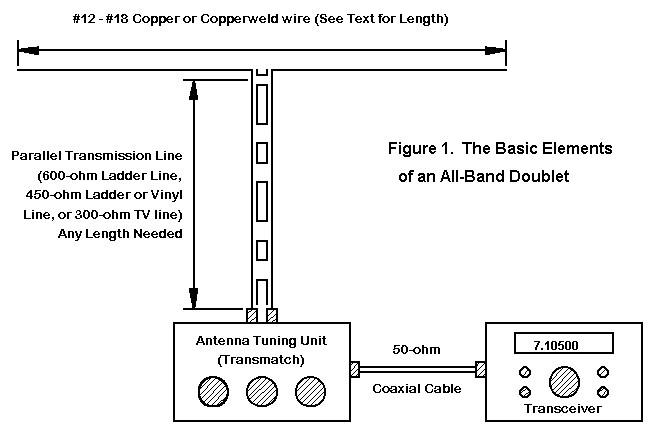
Figure 1. The doublet multi-band antenna (https://ftp.unpad.ac.id/orari/library/library-sw-hw/amateur-radio/ant/docs)
I had to dismiss the idea of replacing all the antennas with one high doublet for 7MHz and above because my roof is too small. However, I already had a full wavelength delta loop (VDL) for 7MHz similar to that in Figure 2, 43 meters of wire high in the air hanging from the tower mast. I sometimes used it on other bands even with high loss in the long coaxial cable feedline. I wondered if it could work on all bands like a doublet if I used parallel feedline instead. I used two PC applications to confirm this, MMANA-GAL (www.gal-ana.de) to model impedances and radiation patterns, and TLDetails for the transmission line calculations. I replaced the coaxial feedline with 16 meters of 400-ohm window line, which was easier than I expected to bring it into my shack.
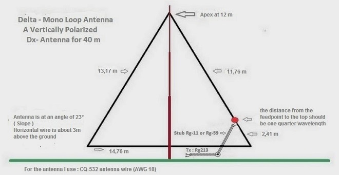
Figure 2. Basic design of a vertical delta loop (VDL) for 7MHz (http://www.on7yk.eu/h-deltaloop.html)
The VDL is one possible variation of a full-wavelength loop, and is known for its good performance and convenience. Only one tall support is needed, and it is easy to adjust by changing the length of only one leg, versus two for a dipole. A full-wavelength loop is resonant on all harmonics, rather than only odd harmonics for a dipole.
Tuning a dipole to resonance can be a tedious task. It obviously is not necessary for a non-resonant antenna, but instead the feedline length is important. If you ever tried a new antenna but did not get low VSWR, the instructions probably suggested changing the length of the feedline. As I worked with the parallel line, I began to understand this is based on science and not just an excuse for poor antenna design.
Any section of transmission line acts as a phase-shifting transformer that inverts complex impedance from source to load (high to low resistance, capacitive to inductive reactance and vice versa), depending on its length and physical characteristics. For a given length, the phase shift varies with frequency, which makes finding the best length of feedline for the whole HF band a process of trial-and-error.
The feedpoint impedance of a fullwave loop is around 100-200 ohms near the fundamental frequency and its harmonics, but on non-related frequencies such as the WARC bands the impedance is much higher and has a large reactive component. The resulting VSWR may be difficult for an antenna tuner to match. Most antenna matching units (aka tuners) use variable capacitors and inductors in a T, L, or pi-network. Significant power can be lost in the inductor at low frequencies, with low impedances, or if the output capacitance is low. By entering different feedline lengths in TLDetails, I found that 400-ohm window line between 13 and 18 meters long would transform all VDL feedpoint impedances to between 100 and 1500 ohms in the shack. I could get low VSWRs with 16 meters of window line but on some bands the tuning was very critical or the output capacitor had to be at minimum. This was near a resonant length on 10MHz, because when I shortened the feedline, the VSWR on 10MHz became higher and the impedance was very reactive. I added more line, and with 17.5 meters of feedline, all bands are back in a close range and I can easily get low VSWR with tuner settings near mid-range.
Many external tuners like my old Yaesu FC-901 have only unbalanced output for coaxial cable. When a balanced feedline is used, a balun or common-mode choke is needed. Sometimes a 4:1 balun is used to shift high impedances down to a lower range that is easier for the tuner to match. I tried several baluns but the best was a homemade 1:1 balun choke that I had used with other antennas. (http:/www.ifwtech.co.uk/g3sek/in-prac/inpr1005_ext_v2.pdf)
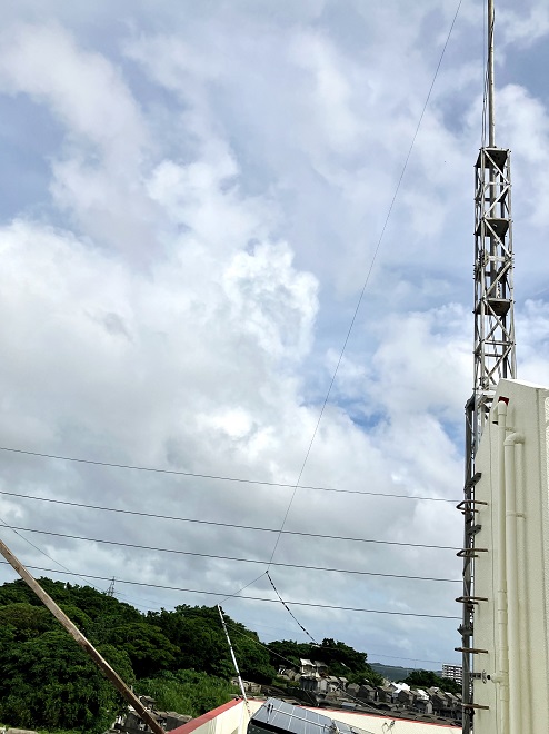
Figure 3. My VDL is supported from the now empty tower mast with the feedline about 1.5 meters up from the corner. (It is not as close to the power lines as it looks!)
According to some antenna experts the relative gain of a VDL is less than a doublet at the same height, so I wasn’t surprised when I compared modeled radiation patterns on their fundamental frequency (Figure 4). In the horizontal plane (azimuth), the dipole’s familiar pattern is stronger than the VDL in the broadside directions but weaker in other directions. The dipole’s high-angle lobe clearly makes it the better antenna for shorter distances. On the second harmonic (Figure 5) the dipole has deeper nulls and the VDL has a strong high-angle lobe, shifting the advantage overall to the VDL, and this is even more pronounced on higher bands.
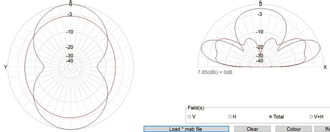
Figure 4. Total (H+V polarization) fields on 7MHz for the 7MHz VDL (red trace) and a 7MHz dipole, 30 meters height (black trace).
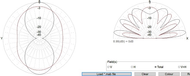
Figure 5. Total (H+V polarization) fields on 14MHz for the 7MHz VDL (red trace) and a 7MHz dipole, 30 meters height (black trace).
Another feature of the VDL is that, unlike a dipole, the feedpoint position of the VDL has almost no effect on the impedance but it does alter the radiation pattern. A low feedpoint gives the best pattern on 21MHz (Figure 6) while on 7, 10, and 14MHz a high feedpoint is better, and there is almost no difference on 18, 24, and 28MHz. The differences are small, so I chose a compromise feedpoint 1.5 meters above a bottom corner.
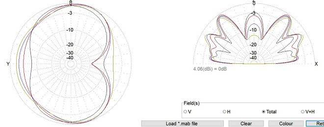
Figure 6. Total radiation pattern with different feedpoints for the VDL on 21MHz. The black trace is almost halfway up one side; gray trace is the lowest point near a corner, and blue and red are intermediate.
Antenna polarization is very important on VHF and higher, but it can also affect performance on HF, especially over middle distances where the polarization does not change much. With DX propagation the transmitted polarization can change randomly but the polarization of the receiving antenna can affect the received signal strength. On 21 MHz, the VDL and the VGP are mostly vertically polarized (Figures 7 and 8), while the dipole pattern is mostly horizontal (Figure 9). The VDL’s combination of vertical and horizontal polarization may give it some advantage over the doublet.
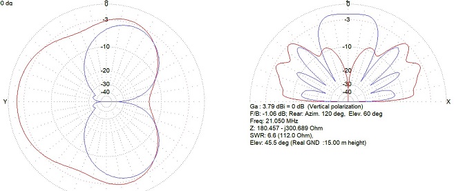
Figure 7. Radiation patterns for a 7MHz VDL on 21MHz. Vertical polarization is red, horizontal is blue.
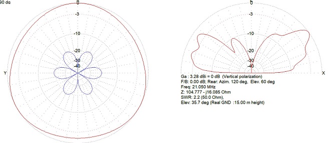
Figure 8. Radiation patterns for a 7MHz VGP on 21MHz. Vertical polarization is red, horizontal is blue.
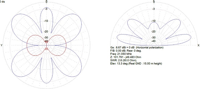
Figure 9. Radiation patterns for a 7MHz dipole on 21MHz. Vertical polarization is red, horizontal is blue.
After several weeks of on-air testing, I was pleased with the results. Except on 14 and 28MHz, I could make instant comparisons by switching from the VDL to another antenna that works on the same band. Often one antenna would be better for some stations and worse for others. Sometimes there was no difference or it might even reverse during a QSO as path conditions changed.
I noticed these differences most on 21MHz because that band is now very active. The radiation patterns for the VDL, VGP, and a hypothetical 7Mhz dipole suggest that the VGP and VDL are approximately equal for DX on 21MHz, but the VDL has high-angle lobes to the northeast and southwest that could explain stronger signals on shorter paths such as Okinawa to mainland Japan (Figure 10).
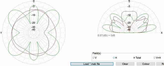
Figure 10. Comparison of far-field patterns for 7MHz VDL, VGP, and dipole on 21MHz. Black trace is the VDL loop, red is the VGP, green is the dipole.
On 18 and 24MHz as well, the VDL has different radiation patterns than a dipole for those bands. The dipole has more gain and a better pattern for medium distances on both bands thanks to the high-angle lobes, but the differences are small at low angles (Figures 11 and 12).
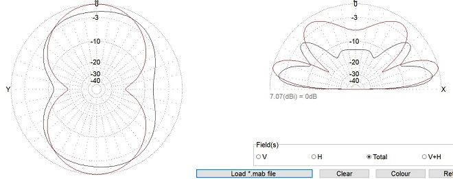
Figure 11. Far-field comparison of the dipole and VDL on 18MHz. Black trace is the VDL, red trace is a dipole.
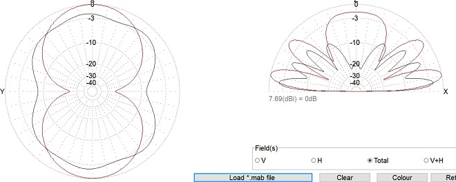
Figure 12. Far-field comparison of the dipole and VDL on 24MHz. Black trace is the VDL, red trace is a dipole.
I change bands often when operating so I had planned to replace the manual FC-901 tuner with an auto-tuner, but after some practice it became easy to make fast band changes. After fixing the final feedline length I used the nanoVNA to find the best antenna tuner settings for each band. I then fine-tuned to get lowest VSWR at the transceiver and recorded the settings. When I change bands now, I preset the tuner dials to the recorded positions and make small final adjustments on the air. It takes only a few seconds, probably as fast as an automatic tuner and perhaps more accurate.
Is the VDL a “super-antenna”? No, but it works very well on all bands. Do I miss the 6 or 7dB gain from the triband Yagi? Not very much, because with the VDL or one of the other antennas I can work almost everyone I can hear with 100 watts. For communicating over a variety of directions and distances, it seems like a choice of fixed antennas is almost as effective as a directional rotary multiband antenna.
Will I enjoy not spending many hours on antenna maintenance? You can guess the answer! If you find yourself in my position, I hope this honest picture of the multi-band vertical delta loop will encourage you to try one for yourself.
From Steve's Workbench backnumber
- Another SOTA antenna, and some thoughts on antenna efficiency
- The Versatile Vertical Delta Loop
- An improved portable Magnetic Loop “Magloop” Antenna
- Small wonder: The Evolution of the uSDX and other QRP transceivers
- I learned about relays by rebuilding some Workbench projects
- Cheap but effective satellite antennas – Part 2: Directional antennas
- Cheap but effective satellite antennas – Part 1: Omnidirectionals
- 18/24 MHz rotatable dipole,“Random-length”, end-fed, multiband antenna
- My shack was a jungle of cables! The solution was a remote antenna switching system.
- Remote Antenna Tuners – Part 2 – Designing, Building, and Testing a Remote Antenna Matching Unit
- Remote Antenna Tuners – Part 1 – Why Use A Remote Antenna “Tuner”