


Short Break
Can the RHM12 portable antenna be matched with a bicycle body on HF?
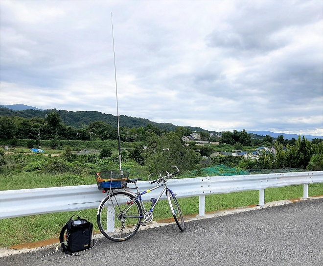
RHM12 installed on a bicycle and IC-705
Plan for carefree HF portable operation
I will try bicycle mobile with the Icom IC-705 and Diamond Antenna's RHM12 in this article.The rig I used is an Icom IC-705 portable radio and the antenna is a Diamond Antenna RHM12. Both are compact, making them ideal for portable operations. Since the rig will be powered by its own battery packs, the maximum power is 5 W. I do not expect to make CQs and receive pileups from many radio stations, but I will be happy if I can make QSOs with them in a reasonable way. I will look at the antenna characteristics after installation.
(1) IC-705
The IC-705 has been available from Icom for about four years now, so it is already widely known. What is surprising about this compact rig is that it can be used in all modes, on all bands from 1.9 to 430 MHz. It produces up to 5 W using the battery pack, and up to 10 W with an external power supply. Until now, compact-body radios have had the disadvantage of being so small that many functions are assigned to a single button, making operation impossible without an instruction manual. The IC-705 was different. It can be operated in much the same way as the company's IC-7300 100 W fixed radio, so it is very easy to use. The UI (User Interface) is well designed.
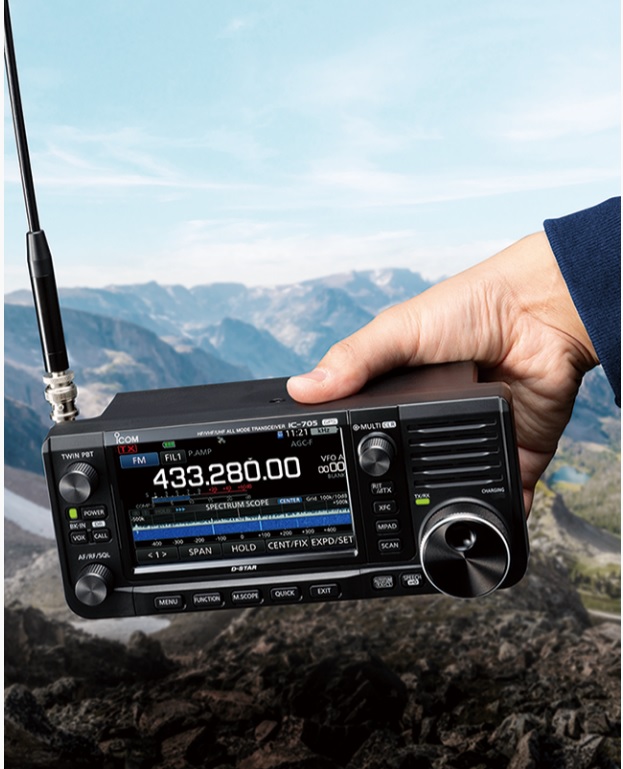
Icom IC-705 (courtesy of Icom's website)
(2) RHM12, Compact portable antenna
Since the Icom IC-705 is a portable radio, I also chose a more portable antenna. The RHM12 is described in the Diamond Antenna company product description as a 7 to 430 MHz portable screwdriver-type antenna. While many roof-mounted HF antennas do not cover the WARC bands, or are optional, this RHM12 covers all amateur bands, including the WARC bands.
In addition, if you purchase the optional RHMC12, it adds coverage of both the 1.9 and 3.5 MHz bands. Even though it is for portable use, the SSB input can be up to 120 W, making it ideal for mobile operation in a car.
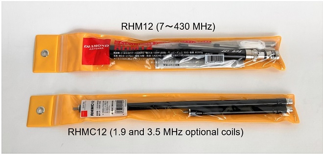
RHM12 (top) and its optional RHMC12 (bottom) from Diamond antenna
Making the antenna base mount
My favorite bicycle is called a cross bike. It looks a little awkward, but I have a metal basket installed on the back of the bike to carry my bag for commuting. The RHM12 will be mounted to this basket through the antenna base mount that I will describe next.

My favorite bicycle: mounting the antenna on the rear basket.
First, I made the base to mount the antenna. I purchased the metal angle and plate shown in ① and ② below at a DIY shop. The material was made of stainless steel to prevent rusting, but it was physically very hard and difficult to drill holes in. The ③ connector is for a UHF female connector and BNC female jack. The RHM12 is attached to the UHF connector side, and the coaxial cable connecting the radio and antenna is connected to the BNC side. Stainless steel screws are used for mounting.
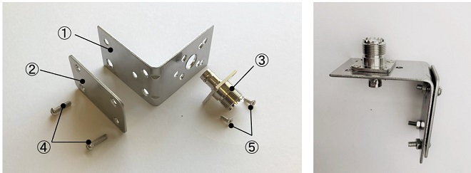
Parts required to make the antenna base (left) and the completed antenna base mount (right)
Installation of the antenna base mount
I attached the antenna base to the basket on the inside as shown in the picture below and fastened it with screws from the front side using the metal plate fittings shown in ②. Also, I grounded the antenna base and the bicycle body firmly with a thick braided wire.
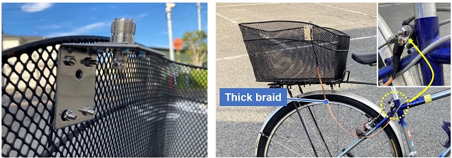
Antenna base attached to the basket (left) Connected to the bicycle body with a ground wire (right)
Installation of the RHM12
The RHM12 and optional RHMC12 contain the components listed below.
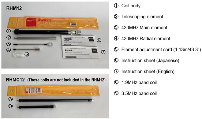
Parts included in RHM12 and RHMC12
(1) Assembling the antenna for 7 to 28 MHz
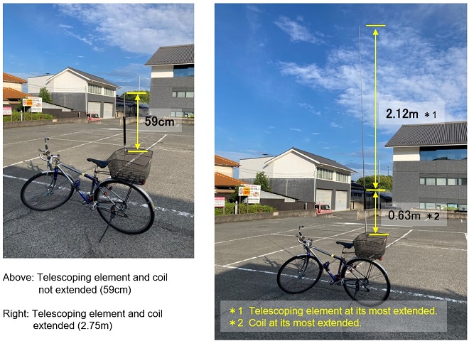
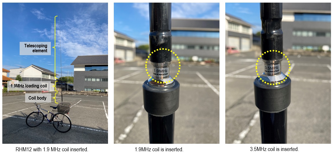
Assemble the elements according to the RHM12 instruction sheet. It is not as complicated, just screw the elements together. The coil part ① is the base of the antenna. There is a loading coil inside, and the inductance of the coil cab be varied by sliding the outer cylinder slides up and down. When the cylinder is extended, the inductance increases, and when it is retracted, the inductance decreases. The base of the coil has a UHF male connector. The base of the coil is connected to the antenna base mount that is attached to the bicycle basket, and the telescoping antenna is attached to the tip of the coil. The installation is screw-type, and no tools are required. Assembly and installation are very easy.
(2) Assembling the antenna for 50 and 144 MHz
The assembly itself is the same as the 7 to 28 MHz assembly described in (1) above, and there is no need to install or remove any other elements. However, since the frequency is higher than that of the HF band, the electrical length of the element is not adjusted by the inductance of the loading coil, but by the length of the telescoping antenna.
The RHM12 comes with an "Adjustment cord" to adjust the element to the approximate length. The length of the cord is 1.13m. When the length of the telescoping antenna is adjusted to match the length of the cord, the total length of the element, including the coil, is 1.46 m at 50 MHz, making it a 1/4 λ antenna. 1.46 m at 144 MHz is approximately 5/8 λ of 144 MHz, which means that the antenna theoretically resonates.
(3) Assembling the antenna for 430 MHz
Assembly of the 430 MHz band antenna is also very easy. Simply remove the telescoping antenna installed for the HF band and install a dedicated 430 MHz band element in its place and attach a radial element to the base of the coil. Both are threaded and require no tools for installation.
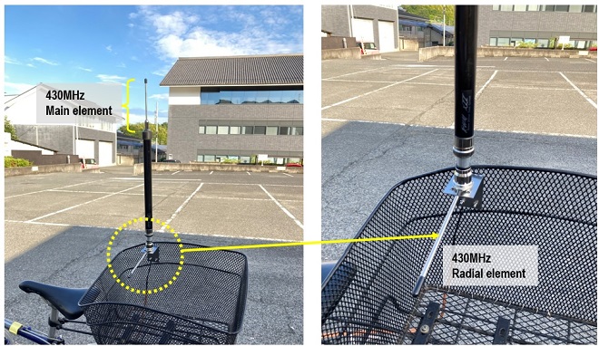
Installation of 430 MHz band antenna
The length of the entire element, including the 430 MHz main element (=13 cm) and the coil (=34 cm), which was replaced with a rod antenna, is about 47 cm. The total length of this element, 47 cm, is approximately 5/8 λ, which theoretically means that it resonates. This antenna is well thought out.
(4) Assembling the antennas for 1.9 MHz and 3.5 MHz
To operate on the 1.9 and 3.5 MHz bands, you need to buy the optional RHMC12, which contains the necessary coils for those bands. Simply attach each coil to the elements between the sliding coil and the telescoping antenna.
Since the physical antenna length of the RHM12 used is much shorter than the wavelength, an additional loading coil such as RHMC12 is inserted into the antenna element. This increases the inductance of the antenna and makes it resonate at the operational frequency.
Adjustment of the RHM12
In my previous portable operations, I had a hard time finding the resonance point, partly because the antenna installation conditions differed each time I moved. I was concerned about this issue, so I brought NanoVNA* with me for the adjustment. I started to adjust from 7 MHz band and worked our way up to the upper frequencies.
*The NanoVNA is a compact, low-cost Vector Network Analyzer.
One of the goals of this experiment is to have a portable operation that looks cool. The instruction manual recommends connecting a counterpoise, but I ignore that and see how far the SWR drops with just the grounding of the bicycle body.
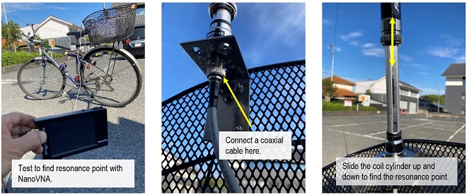
Preparing for the antenna adjustment
The telescoping antenna was extended to its maximum length, and its resonance point was checked with the NanoVNA. Sliding the coil cylinder up and down, I could see the resonance point change on the NanoVNA screen.
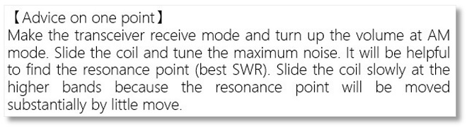
Adjustment advice point described in the RHM12 instruction sheet (taken from the instruction manual)
Following this advice point, I could roughly find the resonance point for each band. The SWR at the point of maximum received noise was 3 or more indicated on the NanoVNA screen at the 7 MHz band. When I checked the resonant frequency with NanoVNA, the resonance point was around 7.5 MHz.
To lower the resonance point, the inductance of the coil needed to be increased a little, so I slid the cylinder up a little. When the resonance point was observed again with NanoVNA, it was a little lower, and after repeating this process two or three times, it was within the band and the SWR became about 1.5.
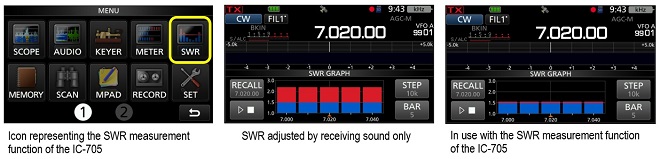
The IC-705 has a function to measure SWR. I confirmed that the NanoVNA is not particularly necessary by using this function.
Adjustment results of the RHM12
The SWR was measured when the RHM12 was not connected to the counterpoise and grounded only to the bicycle body. The SWR for each band is shown below. As mentioned above, the adjustment was made by first finding the approximate resonance point by the received sound, and then using the SWR measurement function of the IC-705, the SWR was driven down to the minimum.
The SWR characteristics below show that the 1.9 and 3.5 MHz bands have an SWR of more than 3, which means that they cannot be used. The SWR of 7 MHz is not good either, but it is about 1.5, and is an acceptable range. The other bands were well below 1.5, which is better than expected.
The 430 MHz band has no adjustment points. When both the main element and radial elements are installed, the SWR was close to 2. It may be acceptable for operations but if it is possible, I would like to keep the SWR below 1.5. When the radial element attached horizontally to the antenna base was angled about 30 degrees below horizontal, the SWR became lower around 1.2 to 1.3 as shown in the screen image. This was not mentioned in the instruction manual, but it seems to be effective.
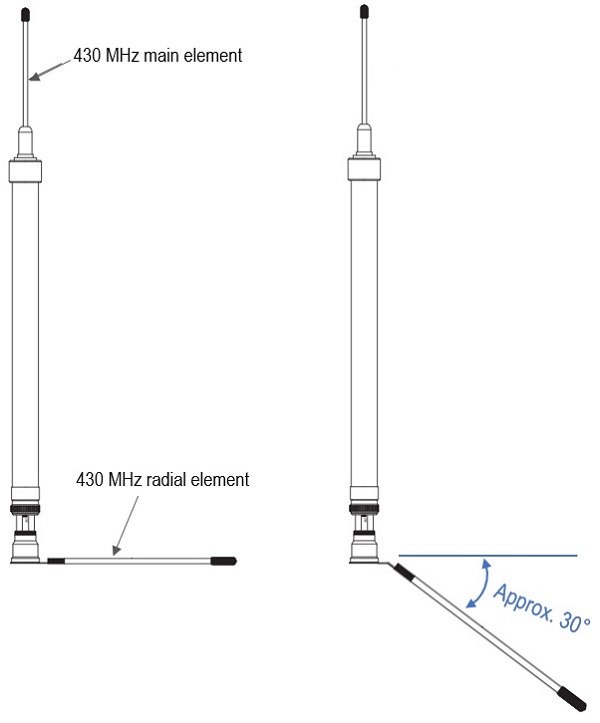
SWR decreased when the radial mounting angle was changed.

SWR characteristics of each band without counterpoise
Additional experiments for reducing SWR on the 1.9 and 3.5 MHz bands
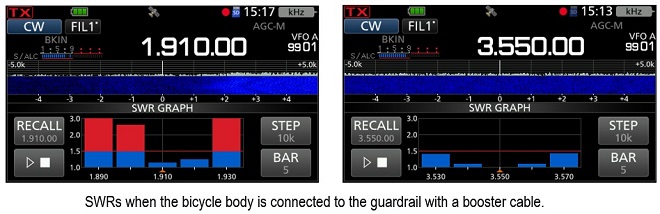
I came up with one idea regarding the SWR drop on the 1.9 and 3.5 MHz bands, and so I immediately conducted an experiment. The results show that the bandwidth is very narrow, but the SWR is less than 1.5.
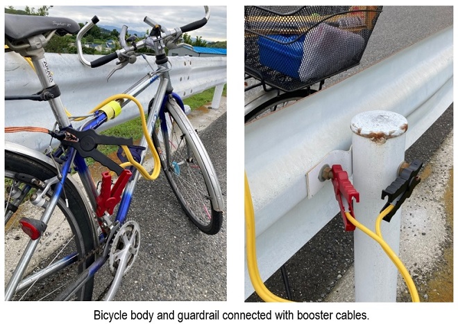
I explained that grounding only the bicycle body resulted in an SWR of more than 3 at both 1.9 and 3.5 MHz bands, as mentioned above. The ground plane was insufficient. The usual method is to compensate for the lack of grounding by counterpoising, but as shown in the photo below, I connected the bicycle body to a nearby road guardrail with a booster cable used to charge a car battery. The result was a perfect SWR reduction.
As you can see from the IC-705 screen capture shown below, the SWR characteristics were about 20 kHz bandwidth at 1.9 MHz and about 40 kHz at 3.5 MHz. This is sufficient because the frequency range of these bands is not very wide.
Actual operation with the RHM12 and IC-705
After adjusting the antenna, I moved to a slightly elevated open space to have real operations on each band. Although a low SWR antenna does not guarantee a good signal, I started watching on the 7 MHz CW band, and was looking for stations that were making CQs and calling them. Unfortunately, I could not beat the pileups of many strong stations and was a helpless state. Still, after several persistent calls, stations picked me up.
Next, I decided to make CQs around 7.015 MHz. After a few CQs, a station called me. After that QSO, it did not continue one after the other, and there were only a few one-time responses. I was able to confirm that the signal was definitely radiated, and the 10 MHz band was similar.
I found it reached well on 50 MHz, 144 MHz and 430 MHz, surprisingly. The received signal was strong and not in a pileup, but when I called a station that I could hear, I got a response almost instantly. I think the antenna on these bands is more efficient because it is not shortened with the loading coil.
It was 33 degrees Celsius outside, the sun was shining, and it was 3 p.m. I tried to make CQs on CW on 1.9 and 3.5 MHz bands. Unfortunately, no one responded. I am sure that the signal was radiated, but I think it is because these bands become active after sunset and many people were not even watching. I will try to operate them another time.
Summary
I have tried various portable antennas in the past, but could not find a resonance point, and had a bitter experience of bringing an antenna analyzer with me even though it was a portable operation.
What I like about the RHM12 is that I can find the approximate resonance point by sliding the coil part of the RHM12 and setting it to the point where the noise or receiving sound is maximum, while listening with the IC-705. Once the approximate resonance point is found, the next step is to use the SWR measurement function of the IC-705 to match the resonance point almost exactly.
I wrote this installation article focusing on the bicycle mobile. As I found out after installation, it is as easy to install as a VHF or UHF mobile antenna if you have a fitting to mount it on the trunk or roof of your car. However, even though it is designed for a portable antenna, and it is quite long when extended, so it must be removed while the car is in motion to prevent accidents due to the antenna falling off.
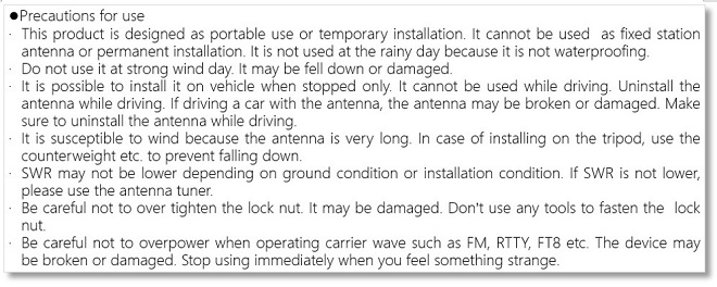
The "Precautions for use" in the RHM12 instruction sheet is pasted below as is for your reference.
CL
Short Break backnumber
- How many colors do you see when a colored disc is rotated at high speed?
- Making a dual Positive/Negative voltage power supply in a single box, for experiments
- Building of an RF Volt-Ammeter for QRP operation
- White noise generator project
- One day electronics project – Making a simple antenna tuner for QRP operations
- Can the RHM12 portable antenna be matched with a bicycle body on HF?
- Making an “ON AIR” lamp using LM358
- Making a simple anemometer
- Making a sound machine say “Good morning. Thank you for everything.”
- Electronics project for the 10 MHz reference signal generator (2)
- Electronics project for the 10 MHz reference signal generator (1)
- Making a straight type AM radio using a TA7642 IC
- About splitters
- Electronics project for FB NEWS: Making a decoration light string
- Making a Simple Electric Field Strength Meter
- Building a simple QRP power meter
- Building a 20 Amp electronic DC load device using an N-channel MOSFET for the load
- Building an automatic backup power switching unit
- Overvoltage protection device using LM358: Part 2
- Building an Over Voltage Protector: Part 1
- Making a 50 MHz monoband MLA without a variable capacitor
- Making a 50 MHz monoband MLA.
- Let's connect a computer headset to the IC-705
- Building a microphone selector
- Building an audio amplifier using an LM386 IC chip
- An External Keypad for Icom Transceivers
- After all, is the receiver good for Up-conversion?
- Find the gain of the stack antenna
- The mystery of controlling the microphone and PTT with only two wires
- RFID tag