


Special SHF Article 3
SHF Operation in the U.S.A.
Super high frequency, or SHF is the ITU designation for 3 to 30 GHz. These frequencies are also known as the microwave and millimeter wave bands. Allocations for Amateur Radio on these bands in the USA are available to all hams except for Novice class operators. All modes are available for operations.
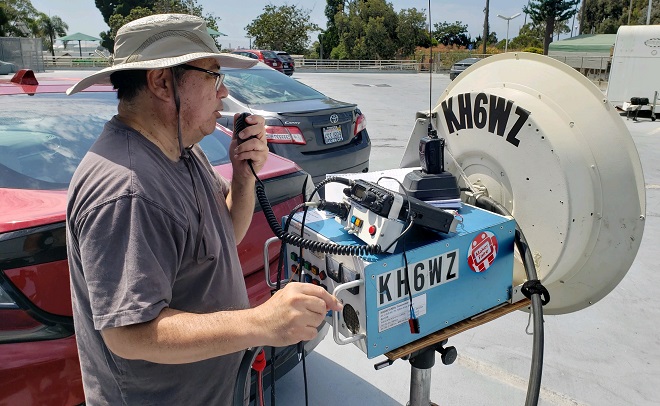
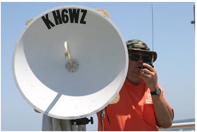
Figure 1. The author operating 10 GHz in Southern California Photo by Neal Jensen N6VHF
Looking at contest results for the ARRL 10 GHz and Up Contest, microwave operation in the USA appears in certain pockets, with the largest area (based on the number of logs turned in) coming from California. This is not surprising, since California has the largest ham population. Microwave operations appear to be influenced by active VHF and up radio clubs in the area, such as the San Bernardino Microwave Society (SBMS) in Southern California and 50 MHz and Up Group in Northern California area.
Also, very active on these bands is US call area 5, with two active clubs, the North Texas Microwave Society (NTMS) and the Road Runners Microwave Group (RMG) in South Texas.
The References section lists several microwave radio clubs, although it is not a complete list. An internet search can find others.
Sometimes, initiating operations on the microwave bands takes a small group of individuals to get started. This cannot be done with one person since operations require at least two stations. Social media contributes to the increased exposure of what can be done on these bands. One example of someone pioneering local microwave activity is Mike King, KM0T, in Northwest Iowa (EN13vc). Mike mentions his fellow microwave pioneers Gene Mitchell NØDQS and Jon Platt, WØZQ. Mike’s website is full of useful and practical information on getting started on a microwave radio journey.
Operations in the USA happen most often in the VHF and above contests. In addition, some radio clubs have “Activity Nights” such as the “Home-to-Home” events by SBMS members. The ARRL Field Day also stimulates microwave activity, and often becomes a great way to introduce HF-only operators and newcomers to the excitement of beyond line-of-sight communications on SHF. Some clubs, including the SBMS, hold field tests (Tune Up Party) to make sure rigs are operating properly before the contest season. These events are also a great way to see how other people construct their rigs, and it can be a fun social event, too.
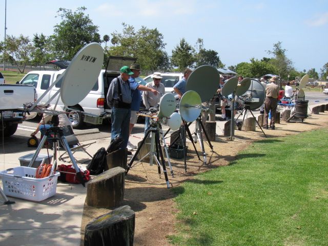
Figure 2. Many clubs hold tune up events to test rigs before the contest season.
In addition to the traditional contest or other operating activity, another unique operating venue can be non-ham radio events, such as local Maker Faire events. Demonstrating ham radio at non-ham events is a great way to promote ham radio to school children as well as non-ham adults in the local community. See Figure 3.
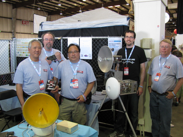
Figure 3. Demonstrating SHF ham radio at Maker Faire.
Left to Right: Brian Yee W6BY, Dennis Kidder W6DQ, Wayne Yoshida KH6WZ, Tony Long KC6QHP, and Mike Lavelle K6ML.
Propagation
One of the most interesting features of the microwave and millimeter wave bands is the wide range of propagation modes. Rain scatter, airplane scatter, tropospheric ducting, and even Earth-Moon-Earth (EME). But even direct path contacts can be affected by reflection, refraction and absorption – just like the way light waves travel through space. The conditions vary as much as the locations and seasons vary. An excellent report on rain scatter by Tom Williams, WA1MBA is posted on the internet, see References section.
Beacons on these bands are very useful as propagation indicators to see if the bands are open. Beacons also serve as useful references for checking frequency stability and accuracy.
For some inexperienced operators who envy the Southern and Northern California mountains, one must mention that high elevations do not necessarily mean longer distance contacts. Sometimes, a high elevation creates a problem: being too high in altitude. In Southern California, there is a condition called the inversion layer, in which a layer of warm, moist air is trapped in between layers of cooler air in the atmosphere. This inversion layer often prevents radio signals from propagating. On the other hand, tropospheric and/or coastal ducting is seasonal and often happens during the summertime contests. See Figure 4.
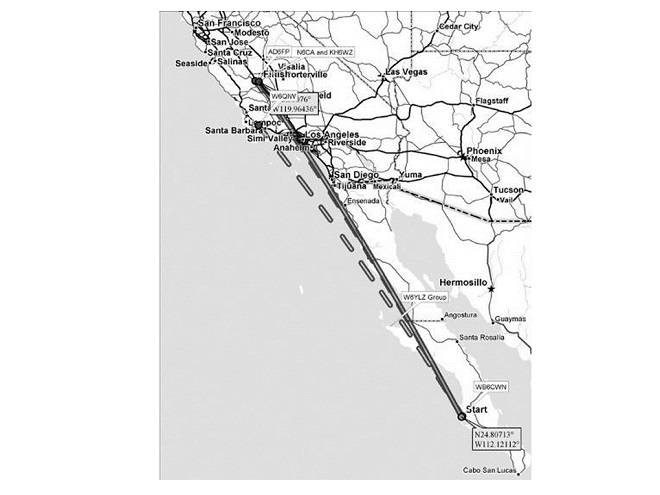
Figure 4. The troposphere duct along the Southern California coastline.
Coastal ducting is caused by an abrupt change in the moisture and temperature of the atmosphere at the boundary between the relatively cool wet layer of air hugging the ocean and the dry warm air above it. This boundary zone acts like a lens for radio and optical signals which follow the curvature of the earth for great distances.
The “secret” for our success in establishing a North America DX record on 10 GHz were the conditions and having the DX stations in place at the right time. During the 2007 10 GHz and Up contest, Chip Angle N6CA and I were rovers in Central California while fellow SBMS member Frank Kelly WB6CWN operated from San Carlos, Mexico as 4C2WH. His Grid Square was DL34wt. Frank made 53 10 GHz contacts from DL34wt on the first weekend. The North America 10 GHz DX record was broken five times, first by Steve Miller, W6QIW from DM04am at 1315 km (817 miles). Steve’s record lasted about seven minutes. Then Chip N6CA and I (KH6WZ) worked Frank from CM94xm (1320 km/820 mi), then again from CM95qi (1426 km/886 mi) and again from DM05ax (1448 km/899 mi). Finally, on August 19, 2007, Gary Lauterbach, AD6FP completed a contact with Frank from CM96wa, a record-breaking distance of 1460 km (907.2 mi). This was quite exciting.
The most popular operating mode on these bands is SSB, but when working the microwave and millimeter wave bands, it is very advantageous to know Morse Code, because of its narrow bandwidth and efficiency. Most long-haul and record-breaking DX contacts are on CW, especially since many propagation modes such as rain scatter distort signals and makes voice communication difficult to understand. Over the last few years, the digital modes are becoming popular, and it will be interesting to see how these newer modes will impact DX records and contest scores.
What Does a Microwave Rig Look Like?
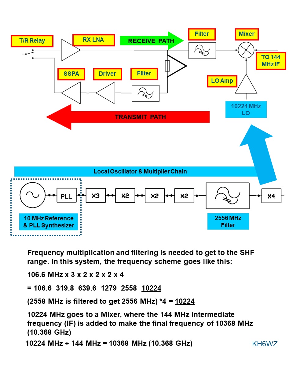
Figure 5. Block diagram of a 10 GHz transverter system with 144 MHz IF
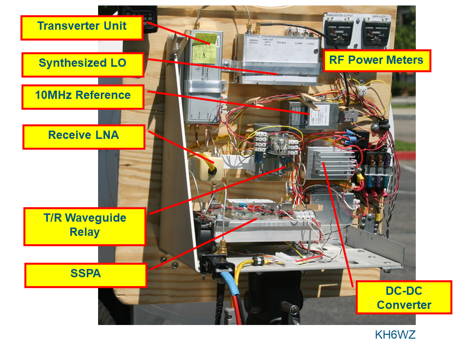
Figure 6. Breadboard 10 GHz rig, following the block diagram
Similar to a customized car (“hot rod,” or perhaps “drift car”), each builder creates a unique system. Since the source of parts and modules varies widely, there is a very wide variation in performance, cost and layout/physical appearance of microwave station equipment. Most SBMS members give their rigs a name after construction is completed. Some examples of completed SHF rigs are shown below.
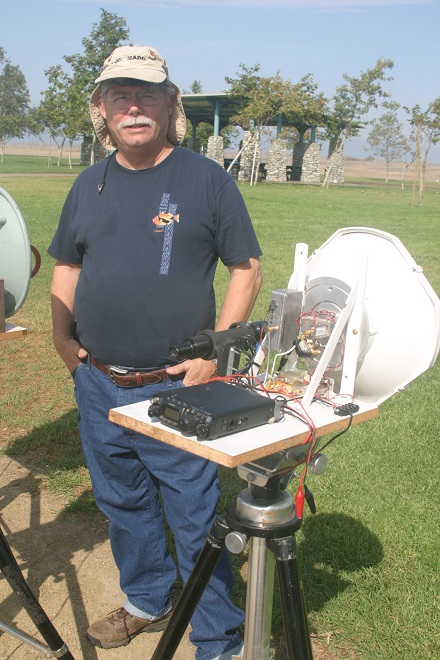
Figure 7. Doug Millar K6JEY with 47 GHz rig
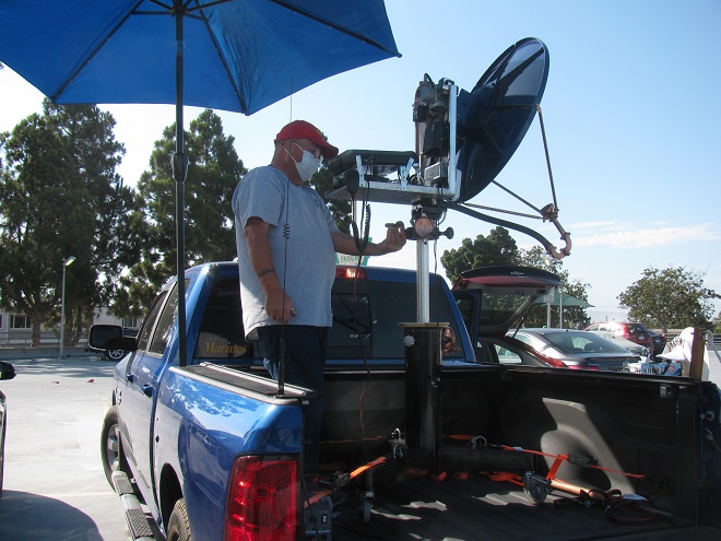
Figure 8. Pat Coker N6RMJ and 10 GHz rig
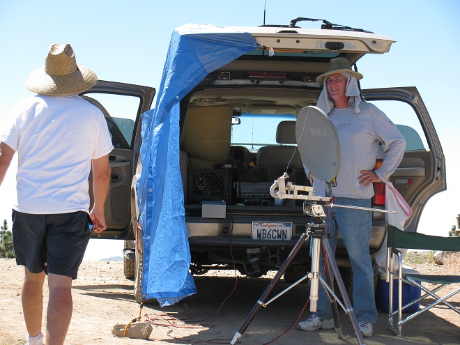
Figure 9. Frank Kelly WB6CWN with mini 10 GHz rig
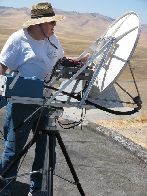
Figure 10. Dave Glawson WA6CGR with 10 GHz rig
There is one off-the-shelf transceiver for the SHF bands, although it is not yet available in the USA also. The Icom IC-905. The Icom website says this rig has 144, 440, 1200, 2400, 5600 MHz coverage. An optional module enables 10 GHz. Power is 10 watts on 144, 440, and 1200 MHz, 2 watts on 2400 and 5600 MHz and 0.5 watts on 10 GHz. The rig includes a GNSS (GPS) module for frequency reference. It looks like a game-changer that may increase activity on these bands.
Components Plus Modules Plus Transverters Plus an IF Unit Equal a Working System
All microwave transverter systems consist of the following elements. Use the block diagram as a guide. See Figures 11 to 14 for examples of surplus 10 MHz OCXOs and other major components necessary for constructing a working SHF transverter system station.
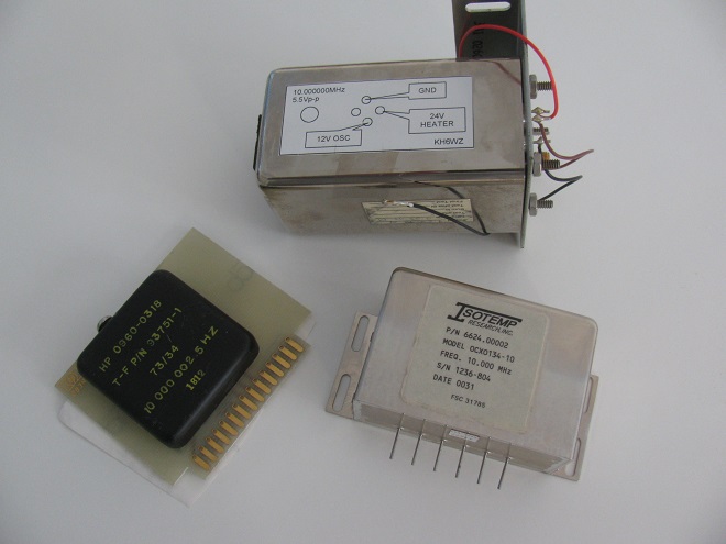
Figure 11. Examples of ovenized crystal oscillators suitable for SHF transverter systems
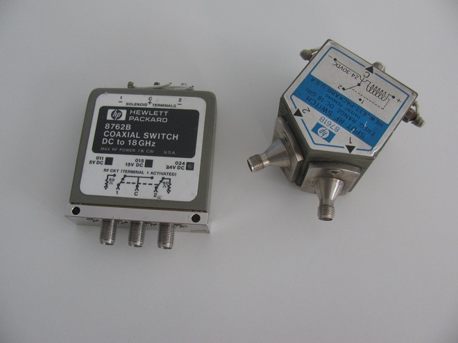
Figure 12. SHF coaxial relays for transmit/receive changeover (T/R relays)
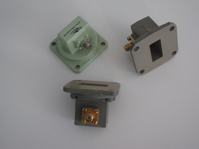
Figure 13. WR-90 waveguide to SMA transitions (adapters)
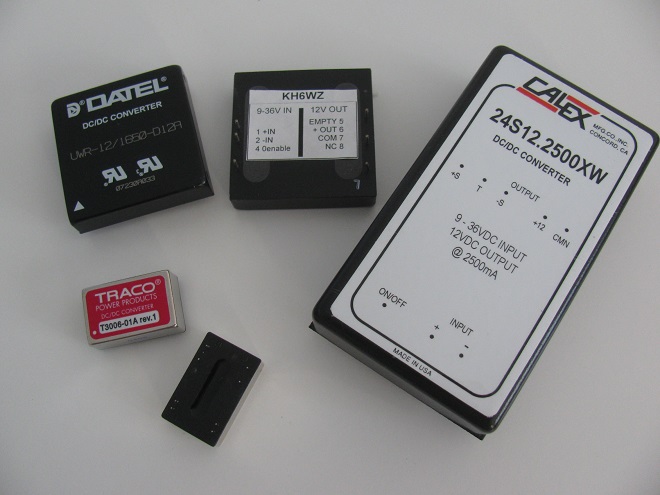
Figure 14. DC-DC boost and buck converters are needed to produce various voltages from the nominal 12V DC power supply. Usually, 24 to 28 volts is needed to drive RF relays.
One of the critical components of a transverter system is the reference and local oscillator since it determines the frequency stability and accuracy. Although frequency control itself does not necessarily need to be accurate and stable, it is perhaps more important for the system to be predictable and reliable. For example, if the operator knows the rig drifts by several dozen or hundreds of Hertz and goes up in frequency, he can compensate for this by tuning the IF radio VFO. However, if the rig is unpredictable in the amount and direction of the rig’s drift, it may be impossible to establish a contact with another station.
On the other hand, if the station has possibly too much accuracy and stability but tries to establish a contact with another station that drifts unpredictably, this will also be challenging to make QSOs with other stations. Even more challenging is a situation with one station drifts upwards in frequency and the other station drifts downwards in frequency. Currently available and affordable are ovenized crystal oscillators (OCXOs) normally used as references in RF test equipment. After a few minutes or hours, these oscillators can be very reliable and stable throughout an entire contest weekend.
When assembling a station, the transverter unit is only one building block or module. The SHF signals must be further converted from RF to audio, and station control (receive/transmit (T/R) change-over) must take place. The conversion from RF to audio usually takes place with an all-mode transceiver operating on an intermediate frequency (IF) for the operator interface, usually a 28-, 144-, or 440-MHz transceiver. See Figure 15.
Figure 15. Transverters require conversion from SHF to and intermediate frequency and finally to audio plus a control interface.
The IF radio is usually an all-mode 28, 144 or 440 MHz transceiver.
Station Improvements
Once a rig is built and working properly, many operators look for ways to improve station performance, which usually means higher contest scores. My microwave journey took me on a path to build and rebuild my 10 GHz rig at least eight times before performance was acceptable, although improvements seem to be never-ending.
One of the first things to upgrade is accuracy and stability. Improvement paths usually begin at the OCXO, in order to improve frequency stability and accuracy. The OCXO could be replaced with a global navigation satellite system (GNSS) or GPS disciplined reference oscillator or a Rubidium standard. Receivers can be improved with better low noise amplifiers (LNAs). Achieving less than 1 dB of noise figure is possible on the ham bands by modifying satellite receiver LNAs or purchasing units designed for the ham bands.
Output power can be increased with amplifiers – solid state power amplifiers (SSPAs), often found on the surplus market. Several years ago, more power meant the use of traveling wave tube amplifiers (TWTs), which are large and require high voltages. However, SSPAs are becoming affordable and more easily found on the surplus market.
The best thing about microwave ham radio is the frequency overlap or compatibility with the non-ham frequencies. In most cases, little to no modification is necessary.
The modification technique called “snow-flaking” may be necessary to optimize performance within the ham bands. This can be an interesting and fun experience, although it also includes some risk, ending up with destroying a precious piece of equipment. See Reference by Chuck Houghton, WB6IGP (SK). Examples of SSPAs in stock at KH6WZ are shown in Figures 16 and 17.
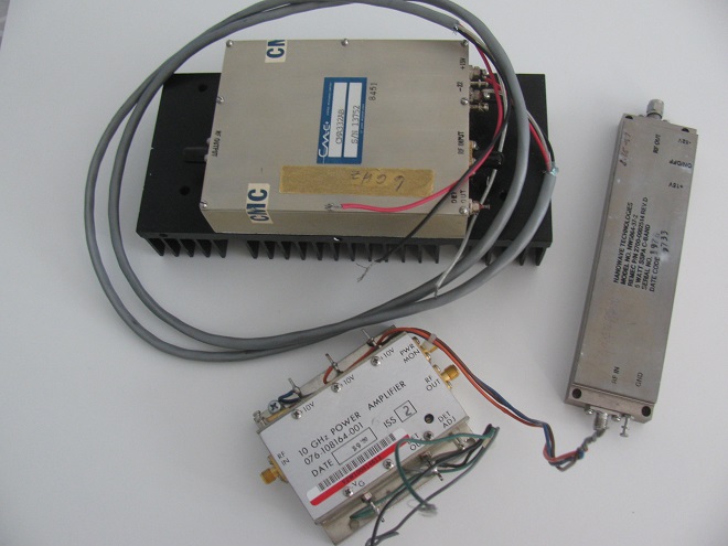
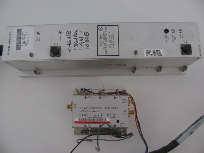
When adding high power to the rig, a sequencer should be added to the transmit/receive path to prevent hot-switching RF to help prevent destroying RF relay contacts. Moving away from coaxial cable to waveguide should also be considered to reduce loss and enhance performance. Two examples of transmit/receive sequencers used at KH6WZ include the N6CA Time Delay Generator and the W6PQL Relay Sequencer, mentioned in the References section.
Antenna Systems
Unlike low-band (HF) operating, there is not much activity on making antennas for the microwave bands. While it is practical to homebrew Yagi or Quagi (Quad-Yagi) antennas for the lower microwave bands (for example Kent Britain WA5VJB Cheap Yagi antennas, see References section), it is much easier to use commercially available kits, surplus dishes or panel antennas for the higher bands.
Surplus satellite TV dish antennas or horns (see Figure 18) are often the first antennas for a first 10 GHz transverter system. It is important to know that a dish antenna can be used for almost any frequency band. That is because the dish is a reflector for the antenna system. The dish feed determines the operating frequency. A great resource for the amateur microwave community is the W1GHZ Online Microwave Antenna Book. It contains very good technical and practical information for antenna systems for these bands.
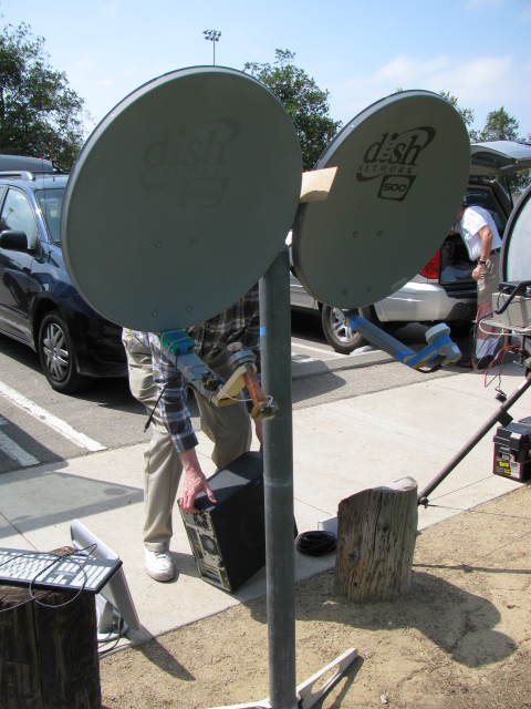
Figure 18. Satellite TV offset feed dishes can often be found at no charge.
In this 10 GHz rig, one dish is used for transmit and the other is for receive.
As an upgrade path, larger diameter dish antennas can be used, or offset-feed dishes for satellite TV reception. See Figures 19 and 20.
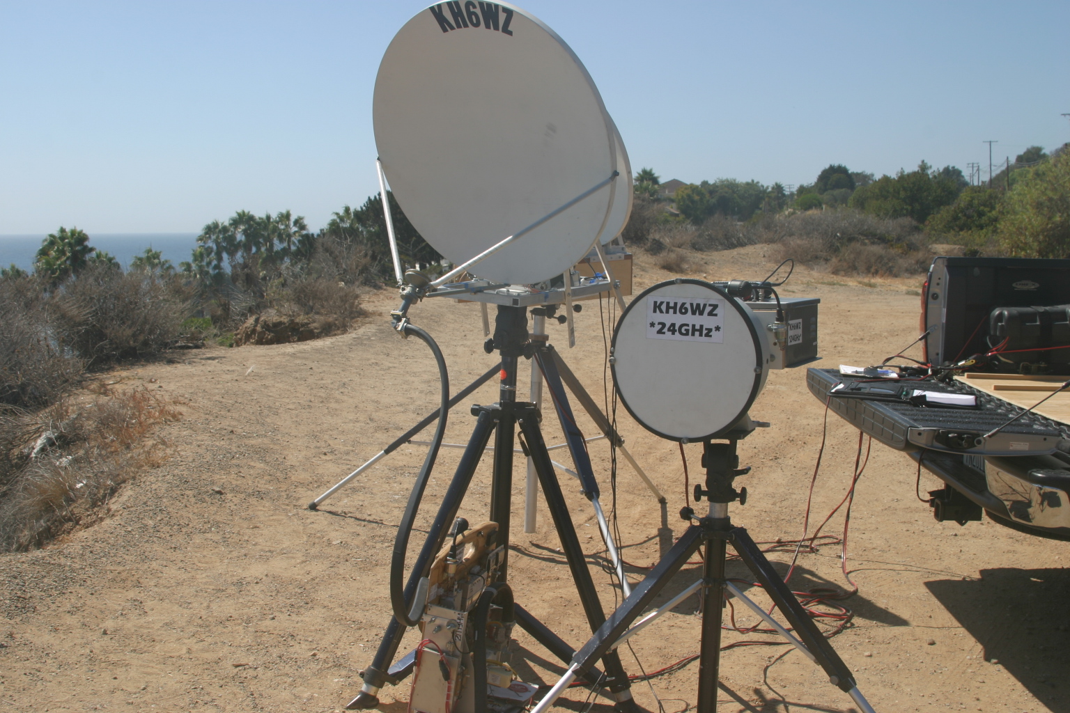
Figure 19. Larger offset feed dishes are a good station upgrade
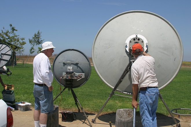
Figure 20. Left: Two-foot prime focus dish used by Dick Bremer WB6DNX. Right: Six-foot prime focus dish used by Robin Critchell WA6CDR
My personal microwave journey is probably typical of most hams. It can be filled with doubts and struggles and disappointments. But the new Icom IC-905 can remove the building and integrating struggle and the operator can then focus on operating and operating techniques.
The SHF bands may become another new frontier for all hams – especially for the hardware hackers and builders. The unique propagation is part of the magic and the attraction for many of us to explore. The small, yet high gain antennas can be another attraction, especially for us who live in “no antennas allowed” residences. Now it may be possible to carry a “Big Gun” station in the back of the family vehicle and enjoy the adventure of radio roving on the SHF bands.
About Wayne Yoshida KH6WZ
Wayne Yoshida is a Technical Writer and CQ Amateur Radio Magazine columnist who brings a cornucopia of writing, editing, technology and marketing skills to his everyday work.
Wayne’s teenage ham radio hobby influenced his life and continues today, turning various personal interests into an interesting and fun writing, editing, marketing and selling journey. Working with technical products makes Wayne excited about coming to work every day.
His most memorable career event is an example of this. As a consultant Public Information Officer for NASA Mission Control during three Space Shuttle missions, Wayne’s radio hobby combined with his speaking and writing ability to enable fast and accurate responses to news reporters from around the world. Hundreds of articles based on news releases and interviews emphasized the educational value of ham radio and electronics and its viability as an emergency communication system for the space program.
Wayne Yoshida KH6WZ
Ham Radio Highlights
•Most memorable experience: Working at NASA Mission Control during the first manned ham-in-space mission, Dr. Owen Garriott, W5LFL, 1983
•North America Two Way Communication Distance Record on 10 GHz (X band) - 1,448 km / 899.75 mi., August 2007
•Contributing Editor, CQ magazine (“The Beginner’s Corner,” since January 2003, now “The Ham Notebook” since March 2010)
•Worked at ARRL Hq. in Newington, CT as Public Information Officer, 1982 to 1984
•Past president, UCLA Amateur Radio Group, W6YRA
•HF contester and DXpeditioner (W1AW, NK7U, W5RRR, 8P6BBS, 8P4B, 8P9BB, 7J1AFZ, J68DX, J68WZ)
•Licensed since 1976
Wayne Yoshida KH6WZ
Technical & Marketing Writer
wayne@wayneyoshida.com
https://www.linkedin.com/in/waynetyoshida/
https://www.youtube.com/user/KH6WZ
References
Microwave Update (MUD)
MUD is an international conference dedicated to microwave equipment design, construction, and operation. It is focused on, but not limited to, amateur radio on the microwave bands. The conference moves from year to year. Visit the MUD website for location and schedules.
http://microwaveupdate.org/
“Microwaves: Not Just for Leftovers,” by Wayne Yoshida KH6WZ
https://www.slideshare.net/wayne_yoshida_KH6WZ/microwaves-not-just-for-leftovers-13918301
Mike King KM0T
http://km0t.com/
“Microwaves from San Bernardino: A Discussion of the History and State-of-the-Art of Microwaving in this Region,” by David E. Laag, WA6OWD (K6OW)
http://www.ham-radio.com/sbms/historyOW.html
W1GHZ Microwave Ham Radio Pages
http://w1ghz.org/10g/10g_home.htm
VHF and Above Radio Clubs
50 MHz and Up Group of Northern CA
http://www.50mhzandup.org/
Northern Lights Radio Society
https://www.nlrs.club/
Central States VHF Society
http://www.csvhfs.org/
Northeast Weak Signal [N.E.W.S.] Group
https://www.newsvhf.com/
North Texas Microwave Society (NTMS)
http://www.ntms.org/
Roadrunners Microwave Group
https://k5rmg.com/
San Bernardino Microwave Society (SBMS)
https://w6ife.com/
Pacific Northwest VHF Society
http://www.pnwvhfs.org/index.html
Southeastern VHF Society
http://svhfs.org
Antennas
Cheap Yagi Antennas, Kent Britain, WA5VJB
https://www.wa5vjb.com/references.html
The W1GHZ Online Microwave Antenna Book
http://www.w1ghz.org/antbook/contents.htm
Directive Systems & Engineering
https://directivesystems.com/
Construction Techniques and Useful Circuits
“Above and Beyond, Microwave Stripline Retuning Procedures,” by C. L. Houghton, WB6IGP, San Diego Microwave Group
http://www.nitehawk.com/rasmit/mstrp_tu.html
Transmit/Receive Sequencer by Jim Klitzing, W6PQL
https://w6pql.com/relay_sequencer.htm
“TR Time Delay Generator,” by Chip Angle, N6CA
The ARRL Handbook for Radio Amateurs 2001, Chapter 22, ISBN-10: 0872591867, ISBN-13: 978-0872591868
Transverters
Paul Wade W1GHZ
http://w1ghz.org/xvtr/transverter.htm#index
Down East Microwave
https://www.downeastmicrowave.com/default.asp
Kuhne Electronic Microwave Components
https://shop.kuhne-electronic.com/kuhne/en/
Icom IC-905 SHF Transceiver
https://www.icomamerica.com/en/products/amateur/handheld/905/default.aspx
SSPAs
“Harris-Farinon 10 GHz Amplifier for Amateur Radio Use,” by Wayne Yoshida, KH6WZ. This article appears in The Proceedings of Microwave Update 2005.
https://wayne-yoshida-kh6wz.com/2013/07/06/harris-farinon-10ghz-amplifier-for-amateur-radio-use/
Propagation
“10 GHz - A Rainy Day Band,” by Tom Williams, WA1MBA
http://www.wa1mba.org/10grain.htm
“Breaking the North American X-Band Record: XE2 to W6 in the 2007 ARRL 10 GHz and Up Contest San Carlos, Mexico to Central California: 900-Plus Miles,” by Wayne Yoshida, KH6WZ
https://www.slideshare.net/wayne_yoshida_KH6WZ/breaking-a-twoway-10ghz-distance-record