


Short Break
White noise generator project
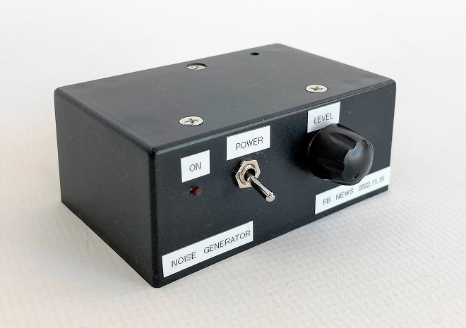
Completed white noise generator
I built an audio amplifier from a kit and wanted to measure its frequency response. So, I made a simple white noise generator.
White noise
In Hi-Fi audio equipment, it is one of the important factors that the output level is linear with respect to the input level of the amplifier. The same is true for linear amplifiers used in amateur radio. Another important factor is that the output signal level does not vary with frequency.
Usually, the input signal level is kept constant while the frequency is varied in frequency response measurements, and the output level is plotted at each frequency. This is a manual measurement and is a basic method, but the basic principle is the same for recent automatic measuring instruments. Therefore, a signal generator that does not change the input signal level with frequency is required. For example, it is known that noise is generated by applying a reverse voltage between the base (B) and emitter (E) of an NPN transistor. Since this noise outputs an almost constant level within a limited frequency range, this signal can be amplified to obtain a constant level signal that does not change much with frequency. The constant level signal is that "buzzing" noise.
If we look at the frequency response graph of this "buzzing" sound signal, the noise is uniformly contained, and the level is flat within a certain frequency range. If this frequency response graph is replaced with the wavelength of light, the noise is called white noise because it corresponds to the characteristics of frequencies that indicate the color white.
Method of generating white noise
Although there are methods using a Zener diode or an operational amplifier, I used the well-known method of applying a reverse voltage between B and E of a transistor. Many people have tried to make this white noise generator by searching on the Internet. Even though the reverse voltage is applied between B and E to generate noise, it seems that some transistors generate noise well and others do not. I have several types of transistors on hand, but for now I tried the general-purpose 2SC1815. Figure 1 shows the principle of generating white noise.
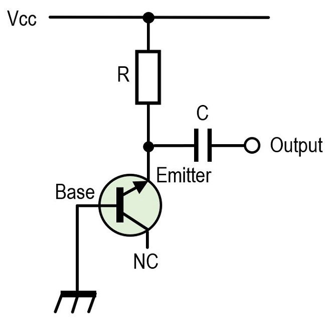
Figure 1. White noise generation circuit (reverse voltage is applied between B and E)
Circuit diagram
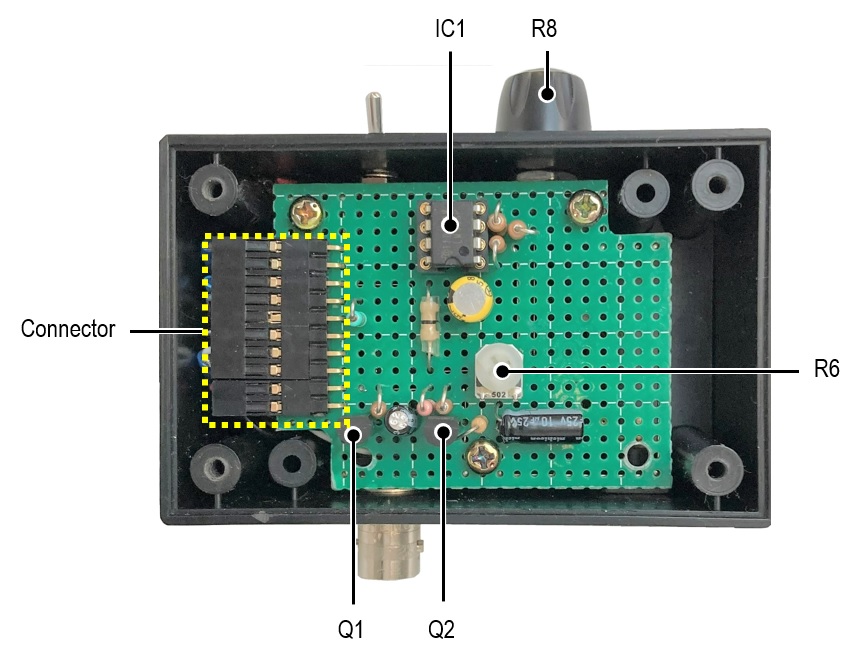
Q1 in Figure 2 is the element that generates the noise. The base of the 2SC1815 is connected to ground, and a voltage is applied between B-E. This voltage is in the reverse direction with no current flow, the opposite of normal operation. The noise generated here is amplified by Q2, and the signal is further amplified by IC1, an operational amplifier.
I use an LM358 for IC1. The unity gain*1 of this operational amplifier is 1 MHz according to the manufacturer's specification sheet. Even if noise is generated in Q1 over a wide bandwidth, the output level will change around the 1 MHz boundary. Also, it can be seen that the frequency response is not constant, even with the reactance of the capacitors between the elements, and so on. However, since the purpose is to measure the frequency response of audio equipment, I will ignore this aspect of the performance.
*1 The unity gain is that the amplification ratio of the signal input to the amplifier and the output signal is 1.
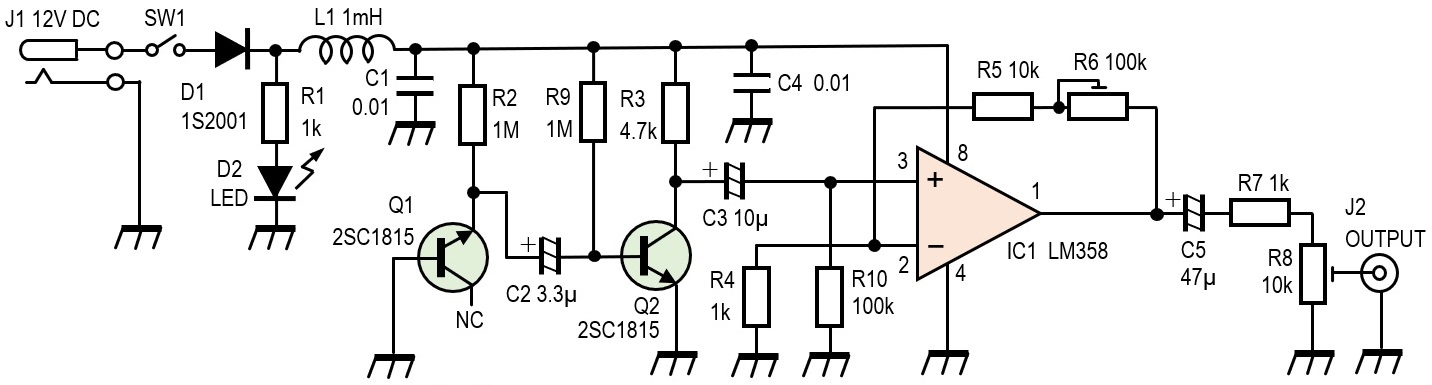
Figure 2. Circuit diagram of the white noise generator
Making the white noise generator
The circuit is simple, so it was built in a small plastic case measuring 8 x 5 x 3.5 cm. On the front panel, I mounted a pilot lamp (LED), a power ON/OFF switch, and a volume control for adjusting the noise output level. On the rear panel, I mounted a DC power jack and a BNC connector for output signals (Figure 3).
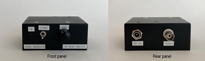
Figure 3. Front and rear panel layout of the completed white noise generator
The PCB allows easy removal with a connector-connection even when circuits are changed. (Figure 4).
Consideration-1
Figure 5 shows the output of the completed noise generator observed on an oscilloscope. It seems strange to be happy with the noise output when I am enjoying electronic construction while struggling every day to produce a clean signal.
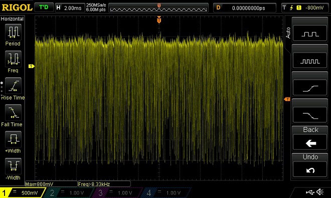
Figure 5. Oscilloscope observation of white noise generator signal
Next, the frequency response characteristics of the noise generator were measured by WaveSpectra*2. As can be seen from Figure 6, the noise level is almost constant, at least in the audio band from 0 to 20 kHz. The vertical axis is the signal level, and the horizontal axis is the frequency in logarithmic scale.
*2 Audio spectrum analyzer developed by Mr. EFU with free application software running on PC
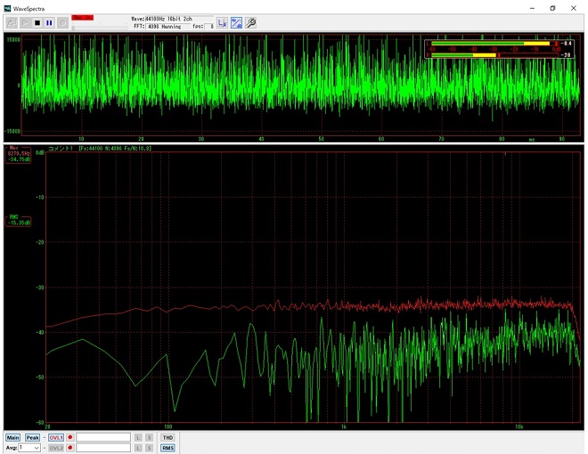
Figure 6. Noise generator output characteristics observed with WaveSpectra
The WaveSpectra is a spectrum scope for the audio frequency range, so it cannot measure a wide range over the RF band. However, the output level of the noise generator was too low and could not be measured.
Consideration-2
In this case, a white noise generator was built for the purpose of investigating the frequency response of audio equipment. If the output of this noise were to extend uniformly to the RF domain, it could be used, for example, to adjust receivers or RF preamplifiers.
As mentioned earlier, the amplifier used in this white noise generator is an operational amplifier, so I know that the frequency response does not extend to the RF region.
In the mid-wave band, the S-meter display showed S=9 or better; in the 1.3 to 1.9 MHz band, it was generally S=7 to 8. In the amateur band, the S-meter waved only up to 7 MHz. Above that frequency range, the noise level was not high enough to cause the S-meter to wander, although it was evident from the loudspeakers that noise was being received.
In the scope screens below, [8] and [9], the frequency changes only 100 kHz, but the S-meter indication changes significantly, probably due to the difference in sensitivity when the IC-705 switches bands. The noise level from these scope images should be used only as a reference.
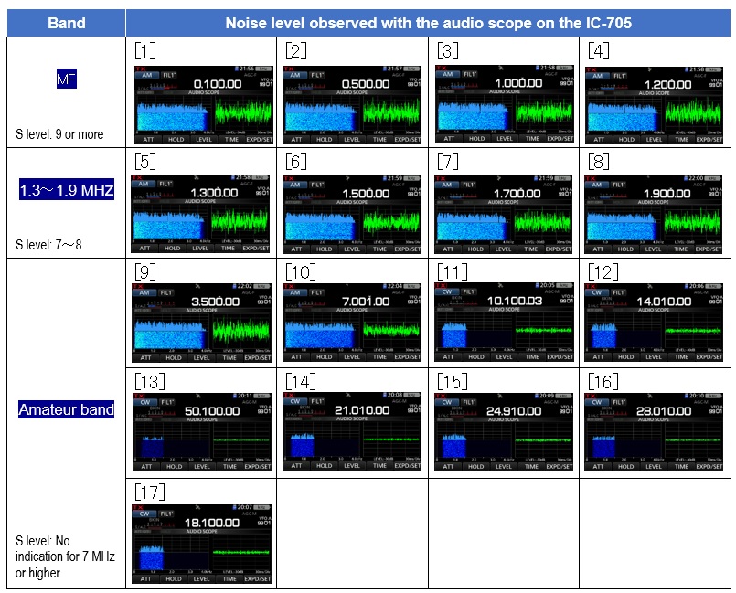
Figure 7. Noise levels in the RF frequency band observed with the IC-705 audio scope
CL
Short Break backnumber
- How many colors do you see when a colored disc is rotated at high speed?
- Making a dual Positive/Negative voltage power supply in a single box, for experiments
- Building of an RF Volt-Ammeter for QRP operation
- White noise generator project
- One day electronics project – Making a simple antenna tuner for QRP operations
- Can the RHM12 portable antenna be matched with a bicycle body on HF?
- Making an “ON AIR” lamp using LM358
- Making a simple anemometer
- Making a sound machine say “Good morning. Thank you for everything.”
- Electronics project for the 10 MHz reference signal generator (2)
- Electronics project for the 10 MHz reference signal generator (1)
- Making a straight type AM radio using a TA7642 IC
- About splitters
- Electronics project for FB NEWS: Making a decoration light string
- Making a Simple Electric Field Strength Meter
- Building a simple QRP power meter
- Building a 20 Amp electronic DC load device using an N-channel MOSFET for the load
- Building an automatic backup power switching unit
- Overvoltage protection device using LM358: Part 2
- Building an Over Voltage Protector: Part 1
- Making a 50 MHz monoband MLA without a variable capacitor
- Making a 50 MHz monoband MLA.
- Let's connect a computer headset to the IC-705
- Building a microphone selector
- Building an audio amplifier using an LM386 IC chip
- An External Keypad for Icom Transceivers
- After all, is the receiver good for Up-conversion?
- Find the gain of the stack antenna
- The mystery of controlling the microphone and PTT with only two wires
- RFID tag