


Short Break
Making a 50 MHz monoband MLA without a variable capacitor
An article about making a 50 MHz monoband MLA (Magnetic Loop Antenna) was published in the April issue FB NEWS worldwide.
As mentioned in the text of the April article, if the parts used in the article are hard to get, most readers just read the article but do not build the device described. So, this time I considered that and made one that uses only easily available components. The component that was difficult to obtain in the previous April issue was the "High voltage variable capacitor." It is difficult to replace the variable capacitor.
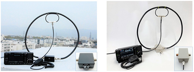
Figure 1. MLA made in the April issue (left) and MLA made in this issue (right)
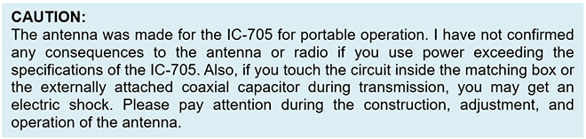
By the way, I will make an MLA this time as well, but please carefully read the CAUTION described below before proceeding with the construction.
Different components of MLA from last time and this time
The capacitor component in the matching box is very different than the variable capacitor normally used. In the April issue, I installed a variable capacitor in the matching box. Since variable capacitors are difficult to obtain, I installed a fixed capacitor instead.
As it is difficult to find capacitors with slightly different capacities, so I decided to make this capacitor using a coaxial cable that is used as a feed line. The MLA matching box made in the previous issue had a knob to turn the variable capacitor, but as you can see in Figure 1, the control box made this time has a like a tail. The only difference is this. There are no changes to the main loop or feeding loop of the MLA.
Make capacitors using coaxial cable
As I will explain the making of capacitors using the coaxial cable in detail in the adjustment section below, the Q of this antenna is very high, and the tuning frequency will change significantly with a slight change in the capacitance of the capacitor. Even in the process of cutting a coaxial cable and adjusting the length, it is important to cut it with the precision of slicing thinly with a cutter knife instead of cutting with nippers and adjusting the length, to put it in an extreme way.
Capacitors made from coaxial cables will be called “coaxial capacitors” in this article. Figure 2 shows the dimensions of the coaxial capacitor that I made. These are the dimensions when using the MLA main loop and feeding loop made in the April issue, so they may not exactly match the ones produced by the reader. The reader must make their own capacitors that match the loops of their antenna, and the environment where the antenna is used.
The coaxial cable I used is RG-58A/U. There is no problem with using other types of coaxial cable. This time, I used RG-58A/U only considering the cost. BNC plugs for RG-58A/U were available at a component shop in Osaka for 100 yen (approximately 1 USD) each. However, one BNC plug for 50 Ω, 3D2V cost 500 yen. Even if I bought several meters of new RG-58A/U coaxial cable, it would be cheaper to make and, so that is the cable I chose.
The principle of a coaxial capacitor is to use the capacitance between the center conductor of the coaxial cable and the braided wire (shielded wire) around it, which act like electrodes. Since the physical distance between both conductors is wide, there is no problem with withstand high voltages.
There is nothing difficult about how to make a coaxial capacitor. If the size of the main loop and feeding loop of the MLA is almost the same as the MLA made in the April issue. The length that the coaxial cables go extend from the BNC plug is 30 mm, and then gradually trimmed to the required length for the desire frequency.
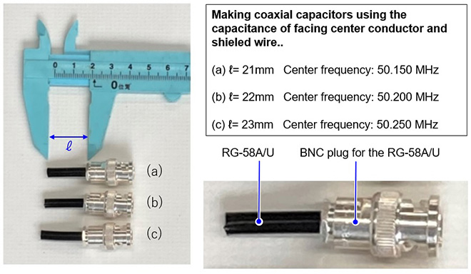
Figure 2. Coaxial capacitor used with RG-58A/U
There is nothing special about installing the coaxial cable inside the BNC plug to be used as a capacitor in this MLA.
Making a matching box using the coaxial capacitors
Figure 3(a) shows the matching box I made for the article in the April issue. There is no variable capacitor inside the new box, and a BNC jack is installed instead of the variable capacitor.
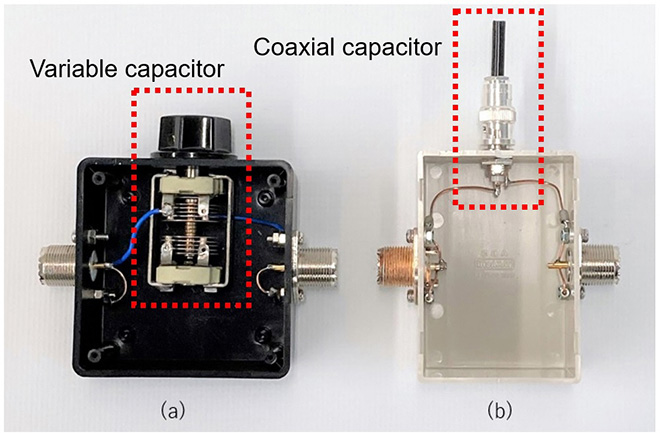
Figure 3. Inside the matching box
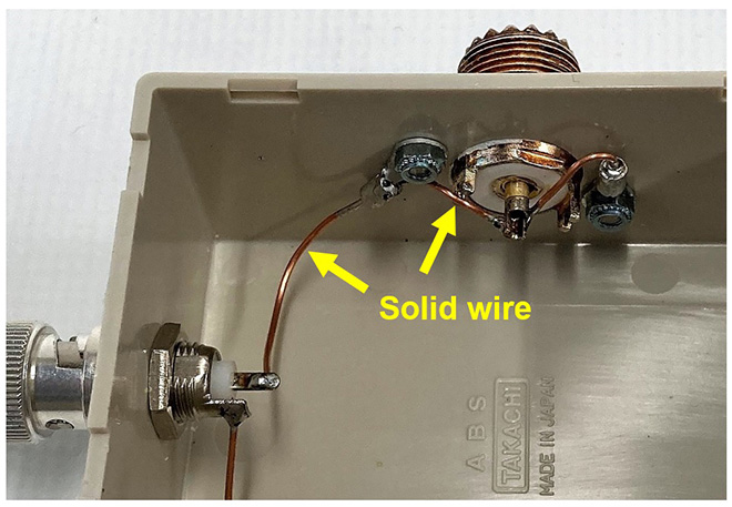
Figure 4. Internal connector wiring
In the wiring inside the matching box in Figure 3(b), the connection between the SO-239 to which the main loop is attached, and the BNC jack is not a thin wire, but a thick stranded wire or a thick single wire that does not move, even after soldering. This is a critical point to make it. (Figure 4) If the wire used for the internal wiring moves due to the vibration of the matching box, the tuning will be off and unstable.
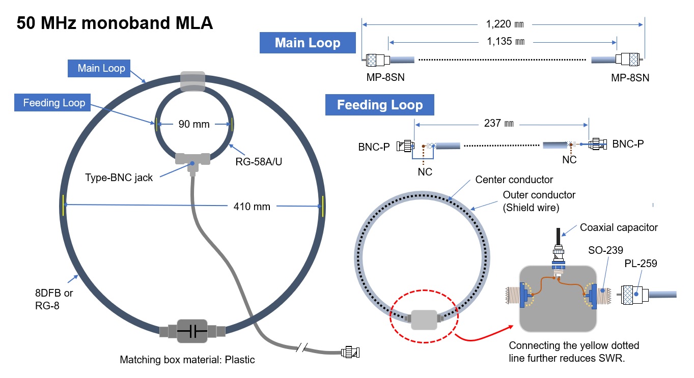
Figure 5. 50 MHz monoband MLA dimensions
Coaxial capacitor adjustment
First, adjust the length of the coaxial capacitor on your bench. Check the tuning frequency with the connection shown in Figure 6. I think the coaxial capacitor has been cut a little too long, so the tuning frequency should probably be in the 40MHz range. If the tuning frequency is already above the desired frequency, the coaxial cable is too short. In other words, the capacitance of the capacitor is insufficient. If the coaxial cable is short, it cannot be adjusted, so it is a good idea to gradually cut a long cable to bring it closer to the desired operating frequency.
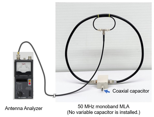
Figure 6. Coaxial capacitor adjustment
If you check the resonant frequency with the antenna analyzer shown above in Figure 6, the resonant frequency may be lower than 50 MHz because the physical length of the coaxial capacitor is slightly longer. The next step is to make the same adjustments in the installation method and for the environment in actual operation and pinpoint the tuning frequency in the vicinity of the operating frequency. When the tuning frequency approaches the desired frequency, the coaxial cable is trimmed with a sharp knife.
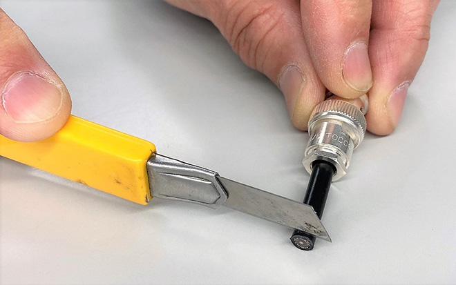
Figure 7. Fine tuning of the coaxial cable capacitor by trimming the coaxial cable
The capacitance of the capacitor is fixed because it uses a coaxial cable. Since the tuning frequency also changes when the operating frequency is changed, it is necessary to make several lengths of coaxial capacitors to set the capacitance that is normally changed with a variable capacitor.
The internal conductor is visible at the cut end of the completed coaxial capacitor, and it is dangerous to touch it by mistake during transmission. You should cover this component with a shrink tube to insulate it. To help distinguish the difference in frequency, use different colored shrink tube on the capacitors.
Completion of the variable capacitor less MLA
Connect the completed MLA to a NanoVNA and check the tuning. (Figure 8) I made 3 different coaxial capacitors in advance on the bench, roughly tuned them, and finally fine-tuned them outdoors.
When observing the tuning dip point with the NanoVNA, the capacitor in (a) was intended for 50.150 MHz, but in reality, it tuned to 50.000 MHz, which is 150 kHz lower. The capacitor in (b) was perfect at 50.200 MHz. In (c), I intended the capacitor to tune at 50.250 MHz, but it seems that the coaxial was cut too short, and the tuning frequency increased to 50.400 MHz, which is 150 kHz higher. You can see the tuning frequency in the yellow characteristic graph of the NanoVNA in Figure 8.
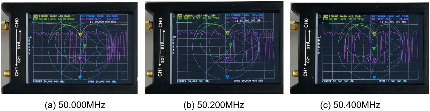
Figure 8. Check the tuning point of each coaxial capacitor
The best coaxial capacitor (b) was connected to the variable capacitor-less MLA that I made this time, and then the antenna was connected to IC-705 to confirm the SWR in actual operation.
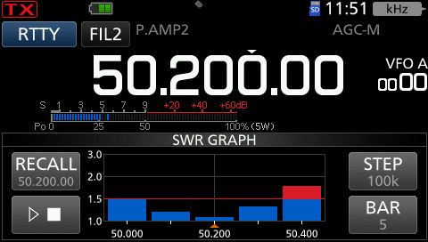
Figure 9. Observe the SWR characteristics with the SWR function in the IC-705
A coaxial capacitor with a tuned frequency of 50.200 MHz was attached, and the antennas SWR characteristics were observed on the SWR graph, one of the convenient functions of the IC-705. The result is shown in Figure 9. The SWR was the lowest when the frequency was around 50.185 MHz. If the SWR is in the range of 1.5, it will pass, and if it is ± 150 kHz with one fixed capacitor, it seems that it can be used without any problem, even without a variable capacitor.
If one of the three coaxial capacitors that I made this time tuned to a frequency of 50.200 MHz, it can output the frequency that many amateur radio operators are usually active on without any switching. If you make a capacitor that tunes a frequency of 50.300 MHz, for example, it seems that you can operate it with an SWR of 1.5 or less from there to around 50.450 MHz, which is 150 kHz higher.
For reference, when I installed a normal 8 pF ceramic capacitor instead of the coaxial capacitor I made, and the resonance frequency was similar. Therefore, it seems that the coax capacitor has a capacitance of about 8 pF.
CL
Short Break backnumber
- How many colors do you see when a colored disc is rotated at high speed?
- Making a dual Positive/Negative voltage power supply in a single box, for experiments
- Building of an RF Volt-Ammeter for QRP operation
- White noise generator project
- One day electronics project – Making a simple antenna tuner for QRP operations
- Can the RHM12 portable antenna be matched with a bicycle body on HF?
- Making an “ON AIR” lamp using LM358
- Making a simple anemometer
- Making a sound machine say “Good morning. Thank you for everything.”
- Electronics project for the 10 MHz reference signal generator (2)
- Electronics project for the 10 MHz reference signal generator (1)
- Making a straight type AM radio using a TA7642 IC
- About splitters
- Electronics project for FB NEWS: Making a decoration light string
- Making a Simple Electric Field Strength Meter
- Building a simple QRP power meter
- Building a 20 Amp electronic DC load device using an N-channel MOSFET for the load
- Building an automatic backup power switching unit
- Overvoltage protection device using LM358: Part 2
- Building an Over Voltage Protector: Part 1
- Making a 50 MHz monoband MLA without a variable capacitor
- Making a 50 MHz monoband MLA.
- Let's connect a computer headset to the IC-705
- Building a microphone selector
- Building an audio amplifier using an LM386 IC chip
- An External Keypad for Icom Transceivers
- After all, is the receiver good for Up-conversion?
- Find the gain of the stack antenna
- The mystery of controlling the microphone and PTT with only two wires
- RFID tag