


Short Break
Building an automatic backup power switching unit
Using a P-channel MOSFET
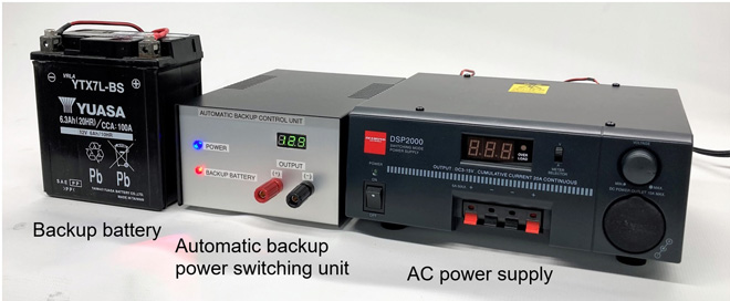
Power outages may occur during bad weather, or where the power regulation system in the area is not good. For those situations, I built a unit to automatically switch from AC power to DC backup power in the event of a power outage.
Specifications of the unit
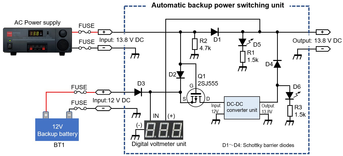
Figure 1 shows the circuit diagram of the power supply switching unit. It is assumed that the transceiver has an output power of 50 watts and is powered by 13.8V DC from an AC powered regulated voltage power supply. Even if an unexpected power outage or failure occurs during operation, and the AC power supply shuts down, it automatically switches to the backup power source, for continuous operation for a certain period of time.
Make sure to connect a charged battery as the backup power source. While operating with AC power, it is possible to charge the battery, but gas is also generated when the lead-acid battery is charged. I didn't include this specification because charging indoors is dangerous. When operating with a power of 50 W, depending on the transceiver to be connected, it will draw approximately 15 A at 13.8 V DC. Consideration must be given to the flow of large currents in the parts and wiring used in the circuit.
Theory of operation
Figure 1 shows the circuit of the automatic backup switching unit. The circuit incorporates a DC-DC converter that boosts the 12 V voltage of the battery to 13.8 V. I didn't make this by myself, but used a commercial unit.
(1) Q1
2SJ555, P-channel MOSFET is used for switching the power supply. The On-resistance value (RDS) when turned ON is as low as 0.017 Ω, and the maximum the drain current (ID) can flow is up to 60 A. The MOSFET used is not limited to the 2SJ555. What is important is the maximum ID current and the On-resistance. Refer to the previous issue of FB Trivia for MOSFET operation details.
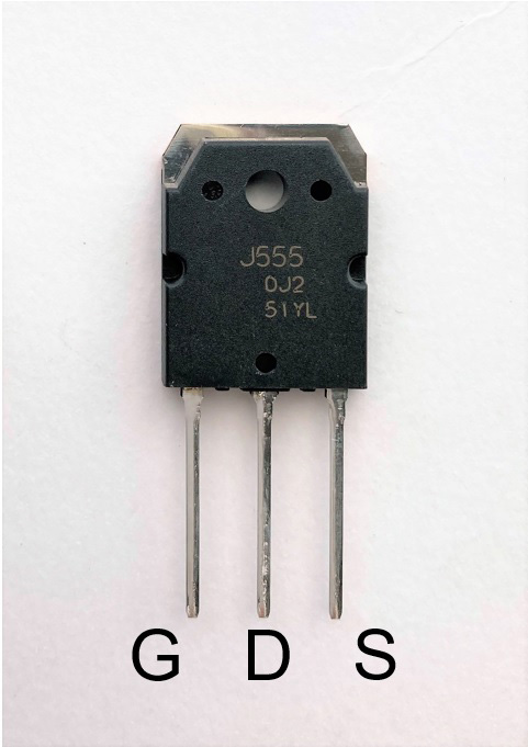
Figure 2. Lead allocation (2SJ555)
(2) D1、D2、D3、D4
These are diodes for backflow prevention. The circuit uses Schottky barrier diodes, which have a lower forward voltage drop compared to ordinary silicon switching diodes, and reverse recovery when a sudden reverse voltage is applied while a forward current is flowing. For reference, the voltage drop of a general switching diode is about 0.6 to 0.7 V, while that of a Schottky barrier diode is as low as 0.2 to 0.3 V. Diodes I use can handle 30 A according to the specifications, and was purchased from a major online shopping site.
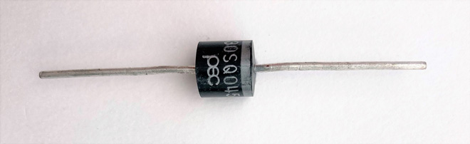
Figure 3. 30 A Schottky barrier diode
(3) D5、D6
These are light emitting diodes (LED). When operating your radio through an AC power supply, the blue LED lights to indicate you are using the AC/DC power supply as the power source. When operating with the backup power source, the blue/red LEDs alternately blink. The blinking LED has a tiny IC chip internally installed in the LED. A 1.5 kΩ resistor is connected in series to each LED so that a current of about 10 mA flows.
(4) BT1
The best backup battery to use is a 12 V deep cycle type that is resistant to repeated charging and discharging, but I had a 12 V/6 Ah maintenance-free battery at hand, so I used it. When using a large capacity battery such as a lead-acid battery, be sure to first charge it outdoors. Charging indoors can be dangerous because gas is generated from the lead-acid battery during charging. Use a backup battery that meets your needs.
<Caution> For safety, be sure to insert a fuse in the cable used to connect the battery to the unit.
(5) DC-DC converter unit
Since the transceiver input voltage is rated at 13.8 V, the DC-DC converter unit boosts the backup battery voltage from 12 V to 13.8 V. This is not what I build in this article, but it was purchased as a unit from a major mail-order site, and it is stated that the maximum current is 30 A. A cooling fan and heatsink are installed underneath the unit. The fan runs automatically by detecting the unit temperature.
Theory of operation in the switching circuit
When 13.8 V is supplied from the AC power supply to the unit, 13.8 V is supplied to the gate (G) of Q1. A voltage lower than the gate voltage by the junction potential voltage of D4 is supplied to the source (S), so Q1 is turned OFF. When Q1 is OFF, the AC power supply outputs as it is through D1. On the other hand, when the AC power supply stops supplying the DC power due to a power outage or failure, the gate voltage becomes zero with respect to the source and Q1 is turned ON. The voltage of the backup battery is supplied to the input of the DC-DC converter through Q1, and the voltage of 12 V is boosted to 13.8 V.
Building the automatic backup power switching unit
I built the circuit on a universal board, and installed it into an aluminum case, together with the DC-DC converter unit. The input terminals that connect the AC power supply and the backup battery are installed on the rear panel of the case.
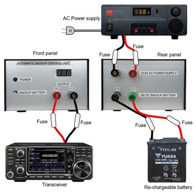
Figure 4. Connection diagram
When the AC power supply shuts down and Q1 is turned on, current flows through the DC-DC converter. Then, it gradually heats up and the small fan attached to the DC-DC converter starts automatically. Considering continuous operation, I used an aluminum case with air-ventilation slits to create an air flow inside the case.
Power switch adjustment and settings
Connect the AC power supply and a charged backup battery to the unit, as shown in Figure 4. Make sure that when the AC power is turned OFF, 13.8 V is output. Since a Schottky barrier diode is inserted in the power supply line in the circuit, the voltage drops by the diode junction voltage. If the DC-DC converter unit you use has an adjustable output adjustment, adjust it to 13.8 V.
Connect your transceiver to the unit output terminals with a DC power cable. Turn ON the transceiver, connect it to a dummy load, and transmit in the FM or RTTY mode. Set the transceiver to transmit in the FM or RTTY mode. At this time, do not set the transmit power to 50 W, but set it to transmit at a low power of a few watts. While continuing to transmit, turn OFF the AC power. If the transceiver continues to transmit without interruption, the unit is working properly.
Summary
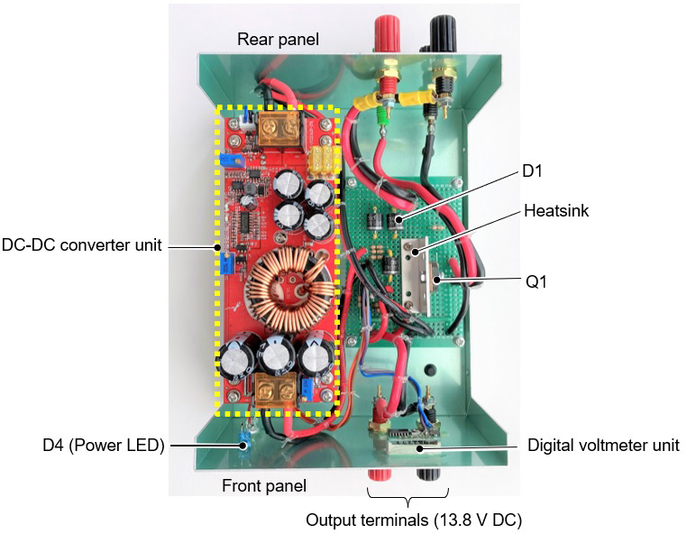
Since the purpose of this project was to operate a 50 W transceiver, I used a relatively large capacity MOSFET, Schottky diodes, and DC-DC converter unit. Also, when assembling the parts on the universal board, I used thick wires (1.6 mm) between the parts. It was stated that the On-resistance of the 2SJ555 is as low as 0.017 Ω described in its data sheet, so I didn't install a large heatsink. In the experiment, in SSB/50 W normal operation, the unit was only slightly warm, even after talking for about 5 minutes. However, in FM/50 W operation, it gets quite hot after 1 minute of continuous transmission. I think the small heatsink shown in Figure 5 is not enough, and I recommend installing a larger heatsink.
For the parts used for the unit and the DC-DC converter unit, select them according to the power specifications of the transceiver you intend to use.
If there is a power outage at night, it is not the same as when you are just rag chewing with friends. You will be in a hurry because the whole house will be suddenly dark. If you connect a 12 VDC lamp to the output terminal of the unit, the lamp will light up, even if there is a power outage or failure, so you can act safely without panic.
CL
Short Break backnumber
- How many colors do you see when a colored disc is rotated at high speed?
- Making a dual Positive/Negative voltage power supply in a single box, for experiments
- Building of an RF Volt-Ammeter for QRP operation
- White noise generator project
- One day electronics project – Making a simple antenna tuner for QRP operations
- Can the RHM12 portable antenna be matched with a bicycle body on HF?
- Making an “ON AIR” lamp using LM358
- Making a simple anemometer
- Making a sound machine say “Good morning. Thank you for everything.”
- Electronics project for the 10 MHz reference signal generator (2)
- Electronics project for the 10 MHz reference signal generator (1)
- Making a straight type AM radio using a TA7642 IC
- About splitters
- Electronics project for FB NEWS: Making a decoration light string
- Making a Simple Electric Field Strength Meter
- Building a simple QRP power meter
- Building a 20 Amp electronic DC load device using an N-channel MOSFET for the load
- Building an automatic backup power switching unit
- Overvoltage protection device using LM358: Part 2
- Building an Over Voltage Protector: Part 1
- Making a 50 MHz monoband MLA without a variable capacitor
- Making a 50 MHz monoband MLA.
- Let's connect a computer headset to the IC-705
- Building a microphone selector
- Building an audio amplifier using an LM386 IC chip
- An External Keypad for Icom Transceivers
- After all, is the receiver good for Up-conversion?
- Find the gain of the stack antenna
- The mystery of controlling the microphone and PTT with only two wires
- RFID tag