


Short Break
Making a Simple Electric Field Strength Meter
I will make a simple electric field strength meter using the QRP power meter published in last month's issue, connecting a wide-band HF to UHF amplifier to the input terminal of the QRP power meter, to measure the weak signal with the QRP power meter. Although it is called a field strength meter, it is not designed to measure the exact field strength, such as V/m (volts per meter) but is just a simple field strength meter to know the relative value of the field strength. I think it can be applied to antenna adjustments, ARDF, or foxhunting.
Outline of the simple electric field strength meter
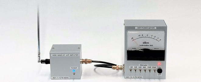
The sensitivity of the QRP power meter itself is such that the meter swings full scale to the full right with a 1 mW (= 0 dBm) input. Even if you connect an external antenna to the input terminal of this QRP power meter, it is not sensitive enough to pick up signals in the air and make the meter move. Therefore, I connected a wide-band amplifier with about 20 dB of gain to the input terminal to increase the sensitivity. The configuration is shown in Figure 1.
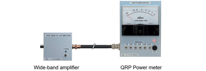
Figure 1. Connecting a wide-band amplifier to increase sensitivity
Calculation of input sensitivity
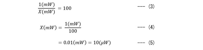
Let us calculate how many mW of power should be input to the wide-band amplifier to make the QRP power meter swing to the rightmost edge. For the QRP power meter itself, without the wide-band amplifier, a signal of 1 mW (=0 dBm) strength was needed to make the meter swing to the far-right end of the scale. In other words, if we input X mW into the wideband amplifier and amplify it by 20 dB, 1mW will be output. We can determine X mW using the equations below.

Figure 2. Amplification of a wide-band amplifier

Since log10 = 1 and log100 = 2, equation (2) shows that 1/X on the right side of log is 100. From this, equations (4) and (5) calculate X mW, which means that when 10 ┬ĄW is input into the wide-band amplifier, it is amplified by 20 dB, and 1 mW is output.
Constructing the wide-band amplifier
Figure 3 shows the amplifier circuit diagram I have created. The key component is the uPC1651G. The IC has already been discontinued, but it seems to be in stock in the market and can be obtained at major mail order shops. If you cannot find it, you can use the uPC1676G, although the physical shape is different. According to the datasheet of this IC, it is possible to get up to 19 dB of gain just by installing a few parts, which is very impressive. According to the datasheet, this IC can cover up to 1200 MHz.
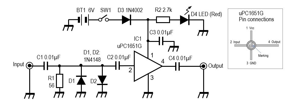
If you search the Internet for ŌĆ£uPC1651GŌĆØ, you will find that many schematics use a 0.001 ┬ĄF (102) capacitor for C1 to C4. D1 and D2 are for protection to prevent signals above 0.7 V from entering. According to the datasheet, the maximum voltage is 5 V. The maximum voltage applied to the IC is kept below 5 V by inserting a diode to force down the junction potential difference of about 0.7 V, because the voltage of 4 AAA batteries in series is higher than 5V. The diode, which lights up when the power supply is turned ON, is designed to be as energy-saving as possible, and a 2.7 k╬® resistor is inserted to reduce the current to about 2 mA or less at 5 V.
Verification of the wide-band amplifier
Figure 4 (left) shows the completed board and battery installed in the aluminum case. Figure 4 (right) shows the PC board. Let us apply a signal to the input terminal and see what the signal level is at the output.
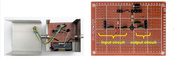
Figure 4. Inside the wideband amplifier
When a 10 MHz, 5 mV p-p signal was input to the input terminal, the output signal was about 30.5 mV p-p. This is 15.7 dB in decibels, which is not quite the 19 dB gain described in the uPC1651G datasheet, but it shows that the amplification is reasonable.
Application of the wide-band amplifier
Figure 5 shows an example of using the wide-band amplifier and the QRP power meter, where the QRP power meter itself only moves the meter a little when it receives the transmitted signal, but the wide-band amplifier actually amplifies it by 15 dB, which is quite useful. The original QRP power meter also has the characteristics of a diode, and I think that it can be used to measure signals up to 50 MHz
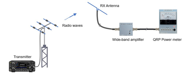
Figure 5. Simplified electric field strength meter using the wide-band amplifier and the QRP Power meter
CL
Short BreakŃĆĆbacknumber
- How many colors do you see when a colored disc is rotated at high speed?
- Making a dual Positive/Negative voltage power supply in a single box, for experiments
- Building of an RF Volt-Ammeter for QRP operation
- White noise generator project
- One day electronics project ŌĆō Making a simple antenna tuner for QRP operations
- Can the RHM12 portable antenna be matched with a bicycle body on HF?
- Making an ŌĆ£ON AIRŌĆØ lamp using LM358
- Making a simple anemometer
- Making a sound machine say ŌĆ£Good morning. Thank you for everything.ŌĆØ
- Electronics project for the 10 MHz reference signal generator (2)
- Electronics project for the 10 MHz reference signal generator (1)
- Making a straight type AM radio using a TA7642 IC
- About splitters
- Electronics project for FB NEWS: Making a decoration light string
- Making a Simple Electric Field Strength Meter
- Building a simple QRP power meter
- Building a 20 Amp electronic DC load device using an N-channel MOSFET for the load
- Building an automatic backup power switching unit
- Overvoltage protection device using LM358: Part 2
- Building an Over Voltage Protector: Part 1
- Making a 50 MHz monoband MLA without a variable capacitor
- Making a 50 MHz monoband MLA.
- Let's connect a computer headset to the IC-705
- Building a microphone selector
- Building an audio amplifier using an LM386 IC chip
- An External Keypad for Icom Transceivers
- After all, is the receiver good for Up-conversion?
- Find the gain of the stack antenna
- The mystery of controlling the microphone and PTT with only two wires
- RFID tag