


Radio Geek
Again, building a simple inductance meter (Part 1)

In the previous and second issues, I wrote a series of articles on the building of a simple inductance meter. The method was to use a tiny variable capacitor for C of the LC resonance circuit in a circuit, and to find the resonance point by varying the capacitance of the variable capacitor to obtain the inductance. Instead of using the tiny variable capacitor, I will create an LC resonance circuit with a fixed capacitor and an inductor (coil) to be measured, and determine the inductance by continuously varying the frequency of the signal supplied to the circuit.
Configuration Diagram for Measuring Inductance
Figure 1 shows a block diagram of a simple inductance meter using the LC parallel resonance circuit shown in the previous issue. An RF signal created by an oscillation circuit is added to an LC resonance circuit through a frequency divider circuit. When the LC resonance circuit resonates with the input RF signal, the impedance of the resonance circuit increases, a characteristic that is used to make the meter in the subsequent stage swing.
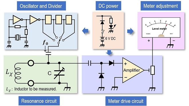
Figure 1. Block diagram of the simple inductance meter building in the previous issue
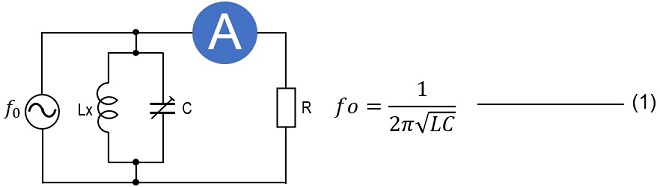
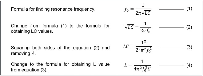
In this case, if the inductance of the coil to be measured, which constitutes a parallel resonance circuit, is L(H) and the capacitor connected in parallel to it is C(F), the resonance frequency can be expressed by formula (1) shown below, which was introduced in the previous article. The formula (4) shown below is a rewriting of formula (1) to obtain the inductance of the coil.
The inductance of the coil is inversely proportional to the square of the frequency added to the resonance circuit from formula (4). In the previous simple inductance meter, the signal added to the resonance circuit was made with a 10 MHz crystal. The 10 MHz signal was added to the parallel resonance circuit, and the resonance circuit was created by varying the capacitance of the variable capacitor. If the frequency of the applied signal is 10 MHz and the capacitance of the capacitor is 500 pF, the inductance of the coil to be measured can be calculated to be 0.5 µH from formula (4).
If a larger inductance is desired, it is necessary to lower the frequency f0 from equation (4). If an RF signal that can be continuously varied over a wide bandwidth like this can be used as a signal source to supply the LC resonance circuit, it should be possible to determine the inductance with a constant C without using a variable capacitor. Figure 2 shows a block diagram of this idea.
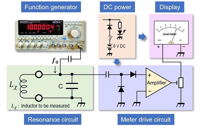
Figure 2. Block diagram of a simple inductance meter using a function generator in an oscillation circuit.
Relation between Frequency and Inductance of Function Generator
Figure 3 shows the value of the inductance of the coil to be measured when the output frequency of the function generator is varied from 100 kHz to 9 MHz, with C constant at 500 pF in the block diagram shown in Figure 2.
Here is how to read the table. First, connect a coil to be measured to the Lx terminal. If the output signal of the function generator is varied and the meter of the display circuit shows a peak around 100 kHz, for example, the inductance of the coil is approximately 5 mH. If the meter shows a peak at a frequency between 100 kHz and 200 kHz, the table shows that the inductance is approximately between 5 mH and 1.25 mH, but the exact inductance is not known. In this case, the exact inductance can be obtained by substituting each value into formula (4) above.
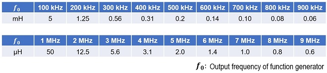
Figure 3. Relationship between function generator frequency and inductance to be measured.
This is a theoretical explanation based on the previous building. The actual building will be in the next issue.
CU
Radio Geek backnumber
- Making a 10-second IC Recorder for copying super-fast CW
- Making sequential turn signals
- Simple Electric Field Strength Meter with LED Display (Part 3)
- Simple Electric Field Strength Meter with LED Display (Part 2)
- Simple Electric Field Strength Meter with LED Display (Part 1)
- Again, building a simple inductance meter (Part 2)
- Again, building a simple inductance meter (Part 1)
- Building a simple inductance meter (Part 2)
- Building a simple inductance meter (Part 1)
- Project No.5 Upgrading the counter to 4-digits
- Project No.4 Making a push-up counter
- Project No.3 Making an Up/Down counter (Part 3)
- Project No.2 Making an Up/Down counter (Part 2)
- Project No.1 Making an Up/Down counter (Part 1)