


Technical Trivia by Dr. FB
Small digital voltmeter, 2-wire type / 3-wire type. What is the difference?
Dr. FB
A digital measuring displays are represented in the block diagram shown in Figure 1. The concept is basically the same, but with the advancement of devices, our electronics projects, as well as mas-productions have changed significantly because we do not need to make a complicated PCB, we just connect the unit to a circuit.

Figure 1. Block diagram of a digital measuring instruments
Figure 2 shows an ICL7136 A/D converter IC chip. The three blocks shown in Figure 1 are built into the IC chip. It has become so versatile that it is also often used in kits, such as a digital multi-meter for beginners. If you want to make a PC board for the IC chip by yourself, instead of buying a kit and process the case to make a digital measuring instrument, it is not easy because the IC has 40 pins.

Figure 2. Block diagram of the ICL7136 A/D converter
Mini digital voltmeter unit
We sometimes want to attach a simple voltmeter to an electronic device we build. A small digital voltmeter like the one shown in Figure 3 is useful. An analog meter is good, but it requires space to install, and is not cheap. However, a price of the digital voltmeter unit is inexpensive. The analog meter depends on the accuracy and model, but even the ones used for electronic projects cost 15 to 20 USD or more each, and the digital multi-meter kit using the ICL7136 costs about 15 USD for the LCD with a PC board. You can get mini digital voltmeter units at major mail-order shops, for example, for approximately 10 USD for 5 pieces.
There are two-wire and three-wire types of the mini digital voltmeter units, as shown in Figure 3. I was curious about what the difference is, and decided to investigate.
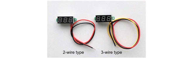
Figure 3. 2-wire and 3-wire mini digital voltmeters (display side)
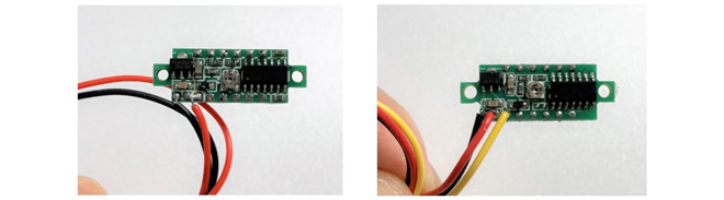
Figure 4. 2-wire and 3-wire type voltmeter (parts side)
What is the difference between 2-wire and 3-wire units?
It is easy to use a mini digital voltmeter. LetŌĆÖs try using two types of voltmeters. First, the red and black leads from both units connect to the DC power supply. Connect the red and black leads to the positive and negative terminals of the DC power supply respectively. The yellow wire does not connect anywhere. Then, apply a voltage for more than 4 V because the minimum operating voltage that the voltmeter circuit operates 4 V, according to its specifications.
At this point, the 2-wire type voltmeter shows the supplied DC voltage on the display. The 3-wire type voltmeter shows ŌĆ£000ŌĆØ on the display. This is because the voltage signal of the voltage point you want to measure is not input to the yellow lead wire. Place the yellow lead on the point of voltage you want to measure and the voltage at that point will be displayed. In other words, if you bundle the red and yellow leads in the 3-wire type, it works the same as the 2-wire type.
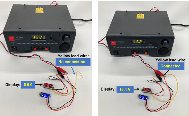
Figure 5. Relationship between the yellow lead and the digital display
In this example, the left blue display shows 13.2, but the right blue display shows 13.1. The last digit of the digital display is not accurate because one digit is always rounded up or down. This is a flaw that digital has.
Applications for the 2-wire and 3-wire voltmeter units
As shown in Figure 6, there are three possible circuits for connecting a digital voltmeter. Figure 7 shows various resistors mounted on a universal PC board for the experiment. The figure shows the voltage at each point, measured by a different accurate digital multimeter, with 10 volts applied to the board input terminals.
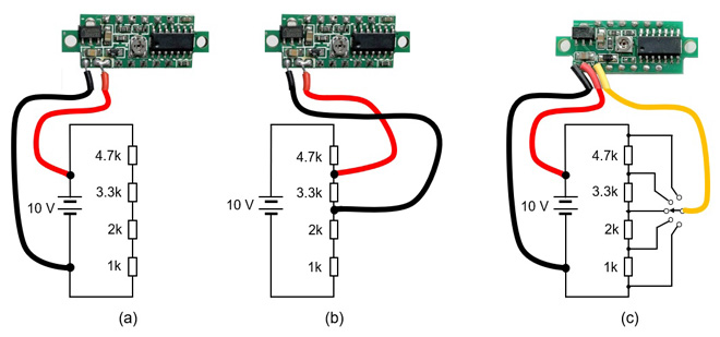
Figure 6. Examples of 2-wire and 3-wire applications
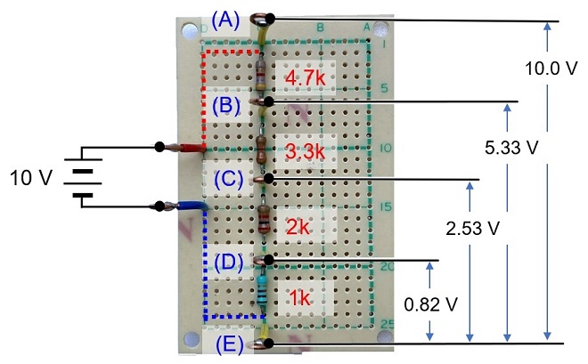
Figure 7. Voltage at each point
Figure 7 shows the circuit shown in Figure 6 (a) assembled using actual parts. I applied 10 V to the input terminals so that voltage between points (A) and (B) is 10 V. Then, I checked the voltage between (B) and (C) across 3.3 k╬® shown in Figure 6 (b) with a digital multimeter. The voltage was 2.8 V. I connected a 2-wire digital voltmeter to the points between (B) and (C), the display was darker than normal, but I could read the displayed 2.8 V. I again measured between (D) and (E), and the voltmeter indicator did not light up at all because the input voltage was 0.82 V. Figure 8 summarizes the voltage at each point with a 2-wire voltmeter. As you can see, it cannot be measured below 4 V.
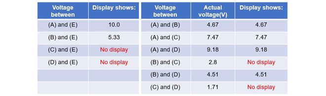
Figure 8. Voltage display according to each measuring point
When a 3-wire voltmeter was connected instead of the 2-wire voltmeter, as shown in Figure 6 (c), the voltage at each point was displayed. From this, if you want to measure a voltage of 4 V or more, you can use either a 2-wire type or a 3-wire type, but if you want to measure a voltage of less than 4 V, you can use only a 3-wire type voltmeter. By using a digital voltmeter according to the circuit, electronic work becomes fun.
FBDX
Technical Trivia by Dr. FBŃĆĆbacknumber
- Generating ŌĆ£Sawtooth WavesŌĆØ using a D/A conversion circuit and a counter IC
- Examining a D/A converter using a Resistor Ladder
- Electronic firefly and its circuit description
- Controlling the rotation speed of a DC motor
- Description of up-down counter using 74HC192 and 74HC4511 ICs
- Considerations when making a dual voltage power supply for operational amplifiers
- Observing filter characteristics with a white noise generator
- Is noise actually reduced in twisted pair cables?
- Experiments on divider circuits using a 74HC74
- Consideration of using a photocoupler as a voltage-variable resistor
- Distorted waveform spectrum as observed on a tinySA
- Trial making of a QFH antenna
- About the inductance of coils
- Operation of analog switches
- Small digital voltmeter, 2-wire type / 3-wire type. What is the difference?
- Constant current circuit using an Op-Amp
- Coaxial cable loss to UHF and SHF
- 2.4 GHz Wireless LAN Antenna
- Let’s use MOSFETS
- 25th Comparator
- The principle of PLL
- Examination of the MLA performance
- About the Fresnel zone of the SHF band
- Level difference under open and load ends of an SSG
- Is “Made in Japan” alive? (UHF adapter again)
- Possibility experiment of passive repeater with the Back-to-Back antenna
- Why you should make SWR measurements just below the antenna!
- How reliable is the L-type BNC?
- Is the Bird 43 accurate enough?
- Does a wire dipole antenna need a balun?
- Why we donŌĆÖt use a silicon diode in a crystal radio?
- How to light the 7-segment LED
- Measurement of Antenna Performance on Handheld Transceivers (Part 3)
- Measurement of Antenna SWR on Handheld transceivers (Part 2)
- Measurement of Antenna SWR on Handheld transceivers(Part 1)
- An SWR meter
- V/UHF 3-Band Antenna Dismantling Note