


Radio Geek
Project No.1 Making an Up/Down counter (Part 1)

Welcome to “Radio Geek” and thank you for your interest in electronics projects. In this corner, I will introduce you to some simple electronic projects, and will build an up-counter using the 74 series logic ICs in the first article. I will develop electronic projects based on this counter from now on.
One-digit counter from 0 to 9
Figure 1 shows a mechanical counter. Each push of a button increases the count by 1. It does not require batteries and does not easily malfunction. I will use popular ICs to electrically operate a similar counter.
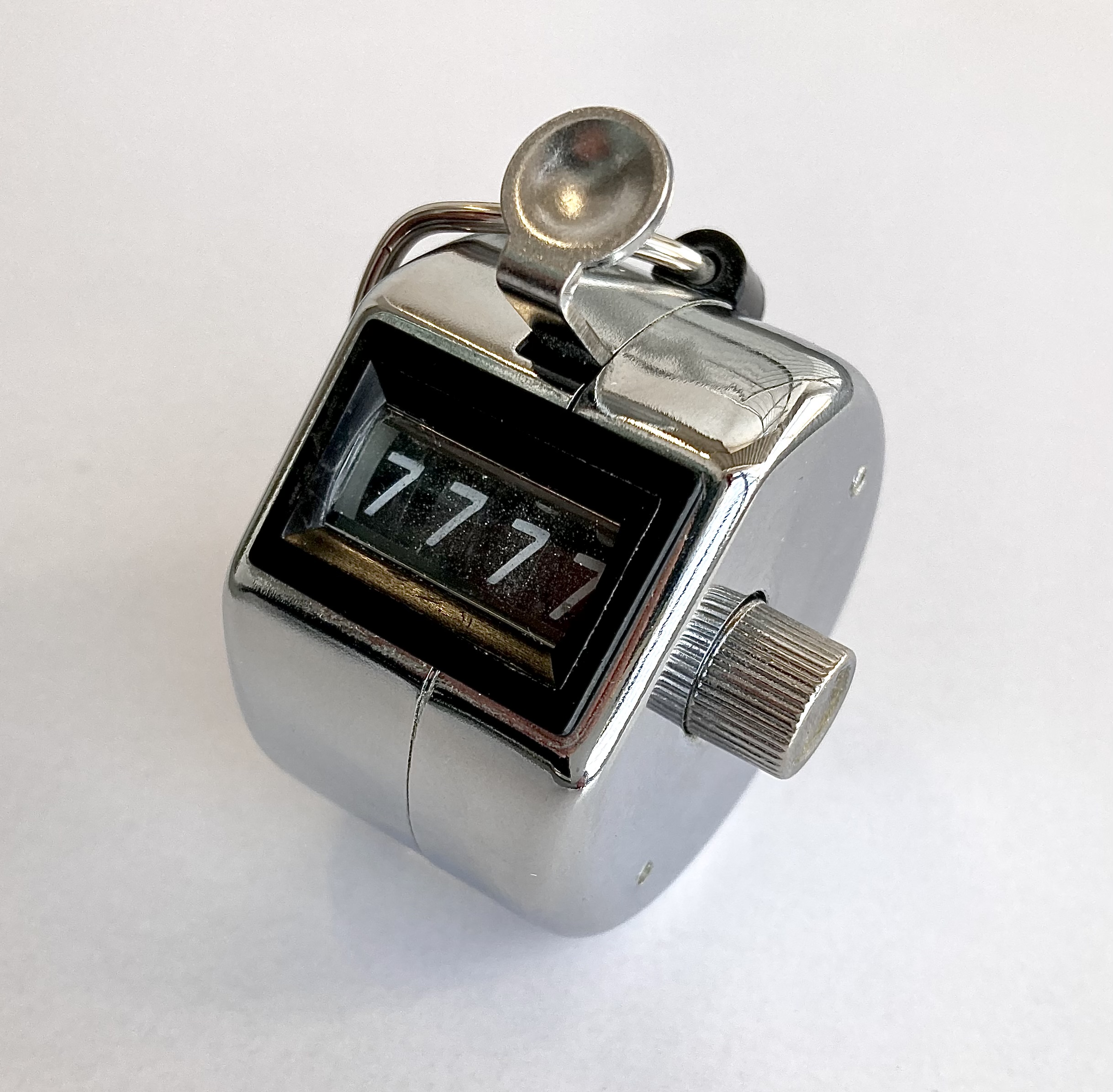
Figure 1. Mechanical counter
Figure 2 shows the circuit diagram of the one-digit up-counter I am going to build. Although one digit is not useful, I will first build a one-digit counter and then expand it to a four-digit counter. IC1 (74HC192) is a presetable synchronous 4-bit up/down counter IC chip that outputs the number of input clock signals in BCD (Binary Coded Decimal) output.
The 74 series includes the 74HC191, 74HC192, and 74HC193 as counter ICs, but I will use the 74HC192 because I had the ICs on hand. This IC can count up and down. First, an up-counter that counts up by "1" when a clock signal is received is made.
IC2 (74HC4511) is an IC chip that lights on 7-segment LEDs depending on the A to D BCD inputs. Since the IC output signal works as an active "H" (called Active High), the 7-segment LED used should be a cathode common LED. Although the part names are not listed, any cathode common LEDs can be used without any problem.
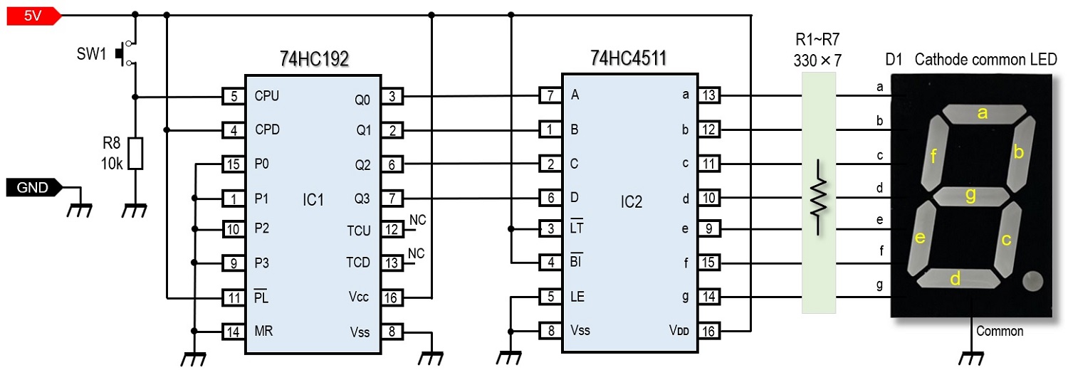
Figure 2. Schematic diagram of the one-digit up-counter
Parts list
In addition to the parts list shown in Figure 3, a 5 V power supply is needed. ICs do not draw much current, but when the letter "8" is lit on a 7-segment LED, at least 80 mA is needed, assuming that about 10 mA flows per segment. If I also consider a little margin, I would like to have 200 mA of current.
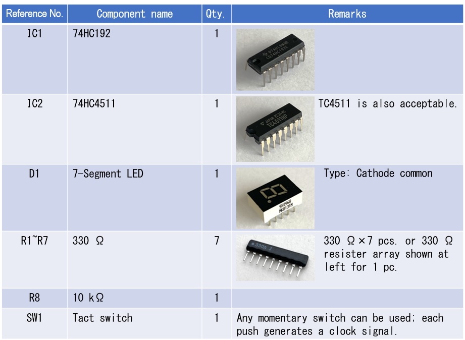
Figure 3. Parts list
Embedded in a breadboard and experimented first
The circuit shown in Figure 2 can be completed by first installing it on a universal board and then placing it in a case. However, since theory and actual operation often differ, I recommend you to first build it on a breadboard to check its operation.
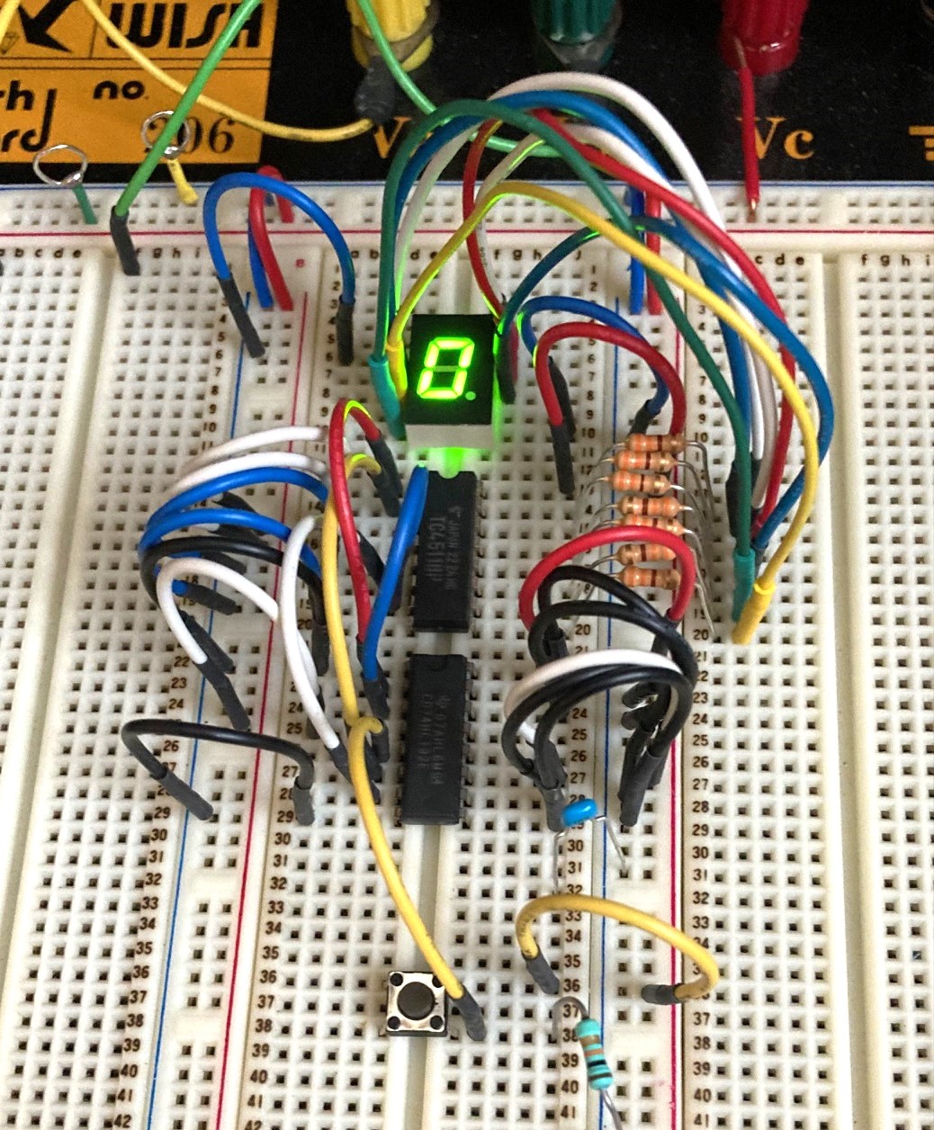
Figure 4. The circuit shown in Figure 1 is assembled on a breadboard
A 330 Ω current-limiting resistor is inserted between the output pins a~g on IC2 and the 7-segment LED. When the output of IC2 goes H, the LED lights up through the 330 Ω resistor. This circuit uses seven 330 Ω resistors, but you can also use a resistor array (see Figure 3) that contains eight 330 Ω resistors in one package. There are not so many parts, so as long as the wiring is correct, it can be completed in an hour.
Confirmation of Operation
When 5 V is applied to the circuit built on the breadboard, the 7-segment LED lights up. The 7-segment LED sometimes shows a number other than 0 (zero), even though no clock signal has been applied yet. When the power is turned ON again, it sometimes becomes 0. The LED display seems to change, depending on when the power is turned ON. The resetting of the IC is perhaps not working. Or it could be that noise from the power supply insertion is causing problems in the circuit. For now, I will leave this issue as it is.
Next, push the tact switch (SW1) that generates the clock signal once. It is no problem if the displayed number plus 1 is shown, but sometimes the number jumps to 2 even though the switch is pushed once at the same timing. It seems that chattering of the switch is occurring.
Summary
In this experiment, I first built a basic one-digit up-counter. For the time being, the 7-segment LEDs go up when the switch is pushed, but as shown above, the operation of the counter is not very clear. This is the end of my work this time. In the next issue, I would like to solve these problems.
CU
Radio Geek backnumber
- Making a 10-second IC Recorder for copying super-fast CW
- Making sequential turn signals
- Simple Electric Field Strength Meter with LED Display (Part 3)
- Simple Electric Field Strength Meter with LED Display (Part 2)
- Simple Electric Field Strength Meter with LED Display (Part 1)
- Again, building a simple inductance meter (Part 2)
- Again, building a simple inductance meter (Part 1)
- Building a simple inductance meter (Part 2)
- Building a simple inductance meter (Part 1)
- Project No.5 Upgrading the counter to 4-digits
- Project No.4 Making a push-up counter
- Project No.3 Making an Up/Down counter (Part 3)
- Project No.2 Making an Up/Down counter (Part 2)
- Project No.1 Making an Up/Down counter (Part 1)