


Technical Trivia by Dr. FB
V/UHF 3-Band Antenna Dismantling Note

Dr. FB
This month we will again feature a 144/430/1200MHz Triple-band transceiver, a 3-band antenna with a single element, covering 144/430/1200MHz for the IC-9700. Some data and materials in the article were provided by Diamond Antenna Corporation.
1. V/UHF 3-Band Antenna
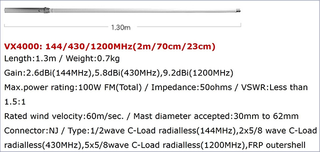
Figure 1. Specifications of the VX4000 (Diamond Antenna)
Look at Figure 1. above. It shows part of the specifications of the VX4000 3-Band antenna. Impedance is described as 50 Ω. If you look closely at the picture posted, there is no radial installed. This means that it is neither a ground plane antenna nor a whip antenna that operates in the same way as a quarter-wave vertical antenna. As far as I know, the antenna is a voltage-fed type when the antenna does not have radials installed.
2. Current feed type and Voltage feed type
As I mentioned earlier, this VX4000 has no radial elements like the ground plane antenna. It is usually called a non-radial antenna. It is devised by an internal matching circuit so that matching can be achieved even without radial elements.
When thinking about antennas, there are methods to separate them by type of power feed. One is “current fed” and the other is “voltage fed.” From an amateur's perspective, there are radials for current fed antennas. There are times when we get a little disturbed because of the radial. The element length is basically λ/2 (half-waves) of that of the voltage fed type. It's also relatively easy to make your own. The non-radial type antenna is mostly a voltage fed type, and its installation is convenient because there is no need to consider the grounding of the mounting part. The radiator element length is basically λ/2, which is longer than the one for λ/4 antenna. Both have advantages and disadvantages.
(1) Current fed type
When installing a λ/4 vertical whip antenna on a car, the shield wire part of the coaxial cable must be securely connected to the car body. This body ground is very important because it acts as the λ/4 vertical ground antenna, which is the same as a grounded antenna.
The current fed distribution curve of the λ/4 vertical ground antenna is shown in Figure 2. The current fed distribution is maximized at the base of the antenna. It is called a “current fed” type.
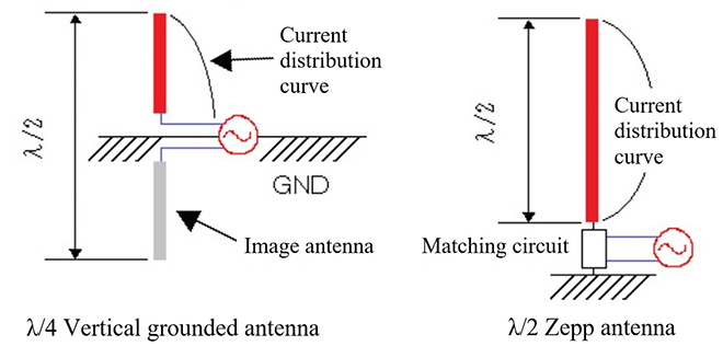
Figure 2. Current fed distributions of a λ/4 vertical antenna and a λ/2 Antenna
(Quote from an article by JA3FMP issued in July 2016)
Figure 3. shows standing waves of the current and voltage distribution on the element of the λ/2 Zepp antenna.
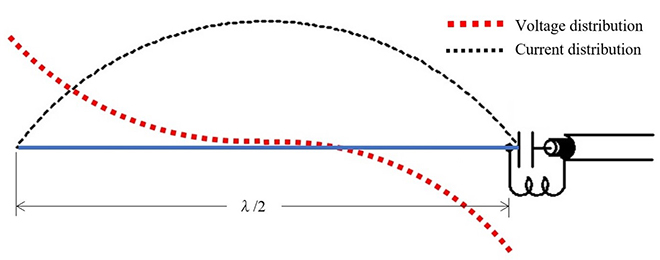
Figure 3. Standing waves on the element of the λ/2 Zepp antenna.
The black broken line in Figure 3. shows the current distribution that is standing on the antenna. The current distribution at the feed point is minimum. With this, the signal received by the element cannot be extracted as power. Contrast with a λ/4 vertical antenna. The red broken line shows the voltage distribution, which is maximum at the feed point. Voltage matching can be achieved by matching the antenna and the feed line.
3. Disassemble of the VX4000
Now we will start disassembling the VX4000. When you loosen the antenna base part screw and pull the N type connector, the element shown in the picture will come out. (Figure 4. middle picture) Sponges are attached to the element as cushioning materials. (Figure 4. lower picture)
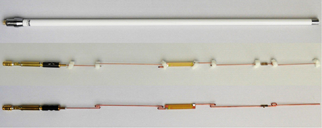
Figure 4. Contents of the VX4000
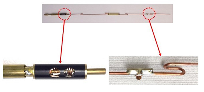
Figure 5. Matching sections of the VX4000
Figure 6. shows each part as an illustration. This illustration was provided by Diamond Antenna. Due to the VHF and UHF bands used, the structure is more complex than expected. If you wanted to make this type of 3-band antenna, it may be impossible to get 50 ohm impedance for all three bands because the structure is very complicated. Honestly, it may be easier and faster to buy an original VX4000 antenna instead of trying to make it by myself. The key point seems to be in the matching part at the base, which is also very complicated and it seems to be like an art.
In addition, Figure 5. shows a picture of the matching part with the black plastic cover removed. I mentioned at the beginning that this antenna has a non-radial structure because it is voltage-fed. We received information from Diamond Antenna that the shape of the sleeve antenna underneath it covered with a black cover works as a filter, and prevents the antenna from being voltage-fed. Let’s dig slightly deeper into the characteristics of this Sperrtopf and below.
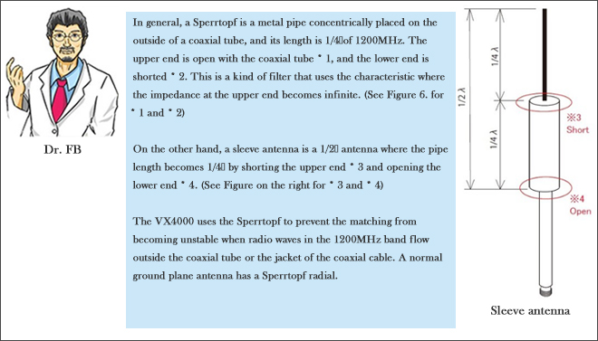
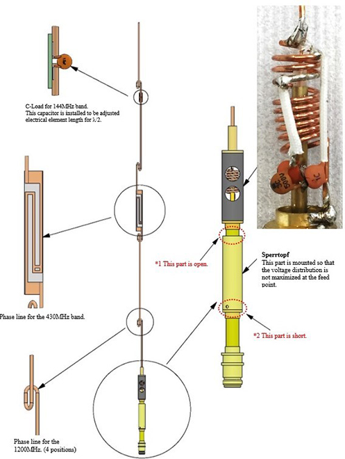
Figure 6. Disassembling the VX4000
4. Standing waves on the VX4000
Figure 7. below shows the status of the radio waves standing in the element for each band.
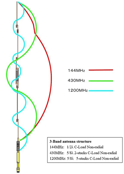
Figure 7. VX4000 Voltage feed curve of the standing waves of each band
5. Antenna vertical directional pattern of the VX4000
Figure 8. shows the vertical direction characteristics. FBDX
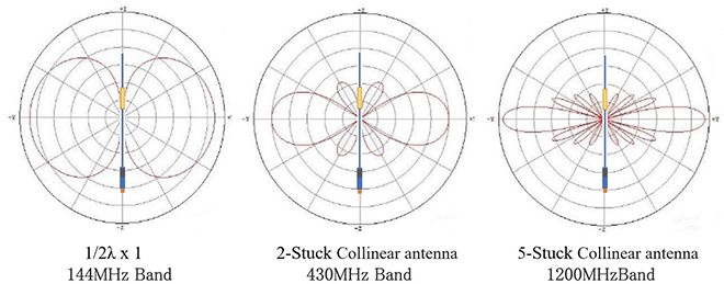
Figure 8. VX4000 Vertical directional pattern
FBDX
Technical Trivia by Dr. FB backnumber
- Generating “Sawtooth Waves” using a D/A conversion circuit and a counter IC
- Examining a D/A converter using a Resistor Ladder
- Electronic firefly and its circuit description
- Controlling the rotation speed of a DC motor
- Description of up-down counter using 74HC192 and 74HC4511 ICs
- Considerations when making a dual voltage power supply for operational amplifiers
- Observing filter characteristics with a white noise generator
- Is noise actually reduced in twisted pair cables?
- Experiments on divider circuits using a 74HC74
- Consideration of using a photocoupler as a voltage-variable resistor
- Distorted waveform spectrum as observed on a tinySA
- Trial making of a QFH antenna
- About the inductance of coils
- Operation of analog switches
- Small digital voltmeter, 2-wire type / 3-wire type. What is the difference?
- Constant current circuit using an Op-Amp
- Coaxial cable loss to UHF and SHF
- 2.4 GHz Wireless LAN Antenna
- Let’s use MOSFETS
- 25th Comparator
- The principle of PLL
- Examination of the MLA performance
- About the Fresnel zone of the SHF band
- Level difference under open and load ends of an SSG
- Is “Made in Japan” alive? (UHF adapter again)
- Possibility experiment of passive repeater with the Back-to-Back antenna
- Why you should make SWR measurements just below the antenna!
- How reliable is the L-type BNC?
- Is the Bird 43 accurate enough?
- Does a wire dipole antenna need a balun?
- Why we don’t use a silicon diode in a crystal radio?
- How to light the 7-segment LED
- Measurement of Antenna Performance on Handheld Transceivers (Part 3)
- Measurement of Antenna SWR on Handheld transceivers (Part 2)
- Measurement of Antenna SWR on Handheld transceivers(Part 1)
- An SWR meter
- V/UHF 3-Band Antenna Dismantling Note