


Technical Trivia by Dr. FB
Measurement of Antenna SWR on Handheld transceivers
(Part 2)

Dr. FB
Because of the question of how to measure the SWR of the antenna attached to a handheld transceiver, we made a jig at the expense of an ID-51 VHF/UHF Dual band handheld transceiver. The SWR can now be measured with the jig. This time, we will introduce the results of measuring the performance of several types of handheld antennas using the jig.
The measured antenna is a 2-band antenna for VHF/UHF handheld transceivers. The length and shape of each antenna are slightly different, but it is printed on the package that the 144 MHz VHF band works at 1/4λ and the 430 MHz UHF band works at 1/2λ. For the measurement, we chose a place where the influence of outdoor obstacles was small. At the end, please see the rare X-Ray photos of the base of each antenna.
1. Measured 4 types of antenna
Figure 1 shows the SWR for each four antenna types. These are the antennas I introduced in the February issue of FB NEWS, which I purchased when I traveled to Taiwan. I think they were made in Taiwan or China, but there was no indication of the "country of origin."
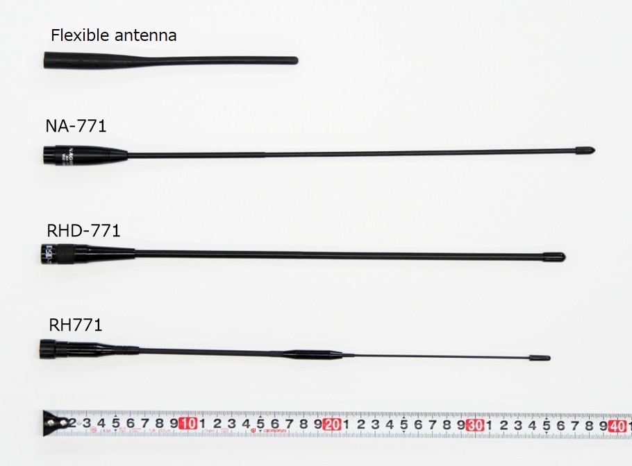
Figure 1. Four types of handheld antennas for SWR measurements
2. SWR measurement #1, the 144 MHz VHF Band
With the connection in Figure 2, the SWR was measured for four types of antennas. The COMET antenna analyzer CAA-500, which has functions of SWR and impedance measurements, was used for the measurement.
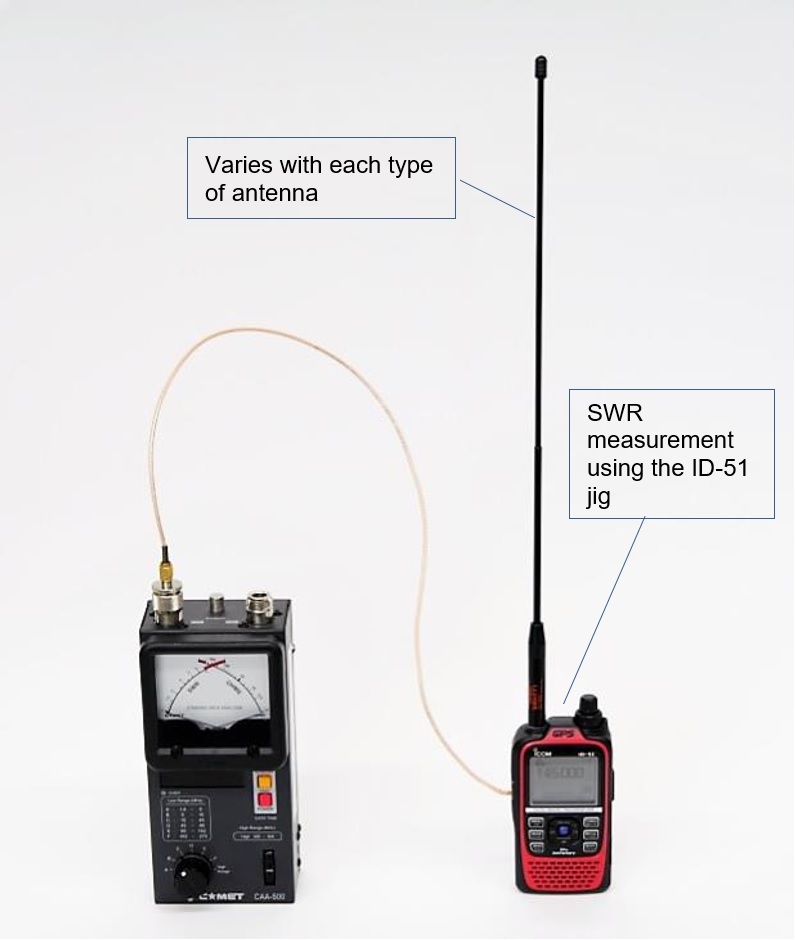
Figure 2. SWR measurement of antenna mounted on handheld transceiver
Figure 3 shows the SWR measured for four types of antennas and the SWR values plotted for each frequency. Since the VHF band operates the same as a 1/4λ vertical ground antenna, the ground is the chassis of the transceiver. Since the chassis has a fairly small ground area with respect to wavelength, sufficient performance as a 1/4λ vertical ground antenna was not obtained, and the proposed SWR was 5-6:1. As a reference, SWR = 5.5:1 is a calculation that when the input is 5 W, about 2.4 W of power returns as reflected power.
Here, I connected the antenna of the handheld transceiver to the magnet base attached to the roof of a vehicle. For a 1/4λ vertical grounded antenna, this is to make sure that the ground plane is really important. The area of the roof of the vehicle is much wider from that of the chassis of the handheld transceiver, so you should get enough characteristics. Figure 4 shows the results, and the SWR is reduced from 5.5:1 when connected to a handheld transceiver to 3:1 or less, indicating that the ground plane plays an important role.
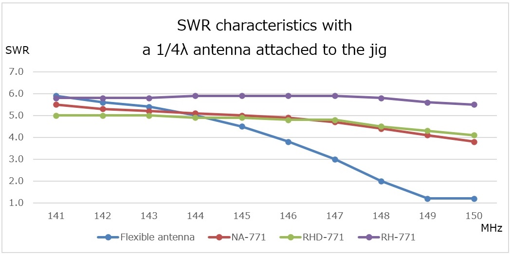
Figure 3. SWR characteristics with a 1/4λ antenna attached to the jig
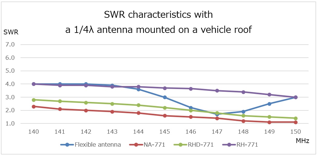
Figure 4. SWR characteristics with a 1/4λ antenna mounted on a vehicle roof
The SWR was further reduced if the handheld transceiver was grasped during the measurement. The SWR of the flexible antenna is 4.5 at 145 MHz, as seen in Figure 3. The SWR dropped to approximately 3:1 when the transceiver was grasped. It is conceivable that the human body and the chassis of the transceiver are C-coupled, and the human body also serves as a ground. From this it can be imagined that the antenna of the handheld transceiver is designed in a form close to actual operation.
3. SWR measurement #2, the 430 MHz UHF Band
Since the 430 MHz UHF band antenna is a 1/2λ antenna, the measurements were made with the expectation that the size of the ground plane would not affect the SWR. The measurement method is the same as for the VHF antenna. Each antenna is attached to the ID-51 jig, and its SWR is measured in the same way with the COMET antenna analyzer. Figure 5 below shows the results.
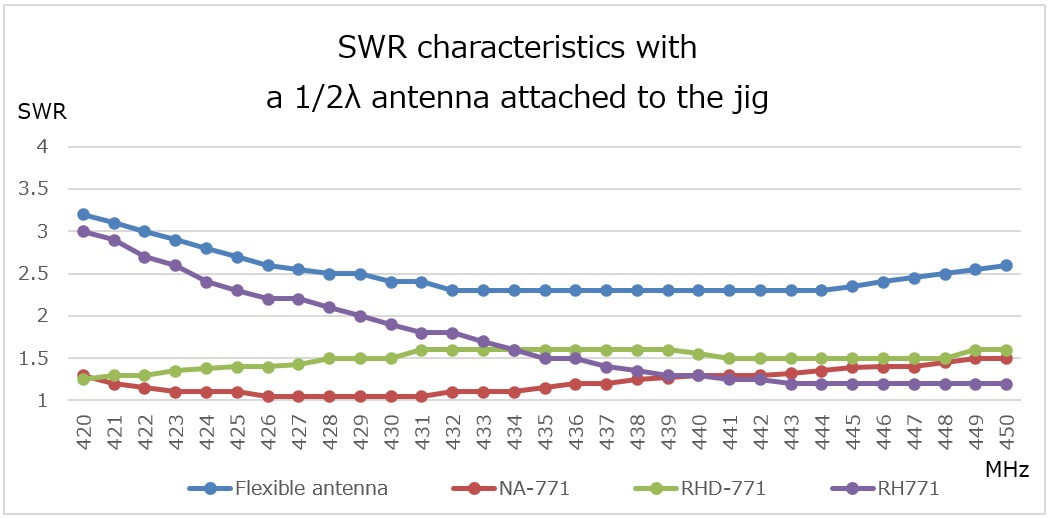
Figure 5. SWR characteristics of the 1/2λ antenna attached to the jig
You can see that quite good results are obtained for each antenna. The SWR in the bands is 3:1 or less. I think the SWR should be lower, but a lower SWR does not mean that radio waves reach longer distances. For example, if a 50 Ω dummy load is connected to the antenna terminal, the SWR is 1:1. Then how about the communication distance? This is the worst communication distance because all RF power is consumed by the resistance in the dummy load, so it hardly goes out as radio waves.
4. X-ray photos of each antenna
Except for the flexible antenna, the other 3 antennas are similar in length and shape. Nevertheless, the differences in SWR can be attributed to the influence of the antenna base and center loading. I am curious what is inside of this molded antenna base. I wanted to break it down and see the inside thoroughly, but after the experiment I want to use it again, so I decided to take an X-ray image of the antennas. We asked the Icom production plant, Wakayama Icom, for assistance. Figure 6 shows the X-ray photos.
In each case, you can see that 2 types of coils are connected in series to the base of the antenna. In the NA-771, in addition to the 2 coils in series, the X-ray photo shows that something like a ceramic capacitor is further connected in series.
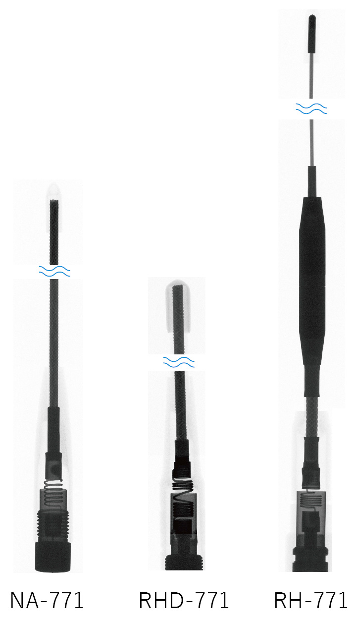
Figure 6. X-ray photos for each antenna
5. Summary
- Even if a 1/4λ type antenna is attached to a handheld transceiver, the SWR does not decrease sufficiently.
- SWR decreases when the handheld transceiver is gripped.
- If a handheld antenna is used in a mobile installation, a certain level of performance can be expected.
- The 1/2λ type antenna is not affected much by the size of the ground.
In part three of this article, we will examine the measurement of the SWR and the radio wave as the final round of "Measurement of Antenna SWR on handheld transceivers (Part 3)." Look forward to the next issue.
FBDX
Technical Trivia by Dr. FB backnumber
- Generating “Sawtooth Waves” using a D/A conversion circuit and a counter IC
- Examining a D/A converter using a Resistor Ladder
- Electronic firefly and its circuit description
- Controlling the rotation speed of a DC motor
- Description of up-down counter using 74HC192 and 74HC4511 ICs
- Considerations when making a dual voltage power supply for operational amplifiers
- Observing filter characteristics with a white noise generator
- Is noise actually reduced in twisted pair cables?
- Experiments on divider circuits using a 74HC74
- Consideration of using a photocoupler as a voltage-variable resistor
- Distorted waveform spectrum as observed on a tinySA
- Trial making of a QFH antenna
- About the inductance of coils
- Operation of analog switches
- Small digital voltmeter, 2-wire type / 3-wire type. What is the difference?
- Constant current circuit using an Op-Amp
- Coaxial cable loss to UHF and SHF
- 2.4 GHz Wireless LAN Antenna
- Let’s use MOSFETS
- 25th Comparator
- The principle of PLL
- Examination of the MLA performance
- About the Fresnel zone of the SHF band
- Level difference under open and load ends of an SSG
- Is “Made in Japan” alive? (UHF adapter again)
- Possibility experiment of passive repeater with the Back-to-Back antenna
- Why you should make SWR measurements just below the antenna!
- How reliable is the L-type BNC?
- Is the Bird 43 accurate enough?
- Does a wire dipole antenna need a balun?
- Why we don’t use a silicon diode in a crystal radio?
- How to light the 7-segment LED
- Measurement of Antenna Performance on Handheld Transceivers (Part 3)
- Measurement of Antenna SWR on Handheld transceivers (Part 2)
- Measurement of Antenna SWR on Handheld transceivers(Part 1)
- An SWR meter
- V/UHF 3-Band Antenna Dismantling Note