


Technical Trivia by Dr. FB
25th Comparator
Confirming the function of a comparator by experiments
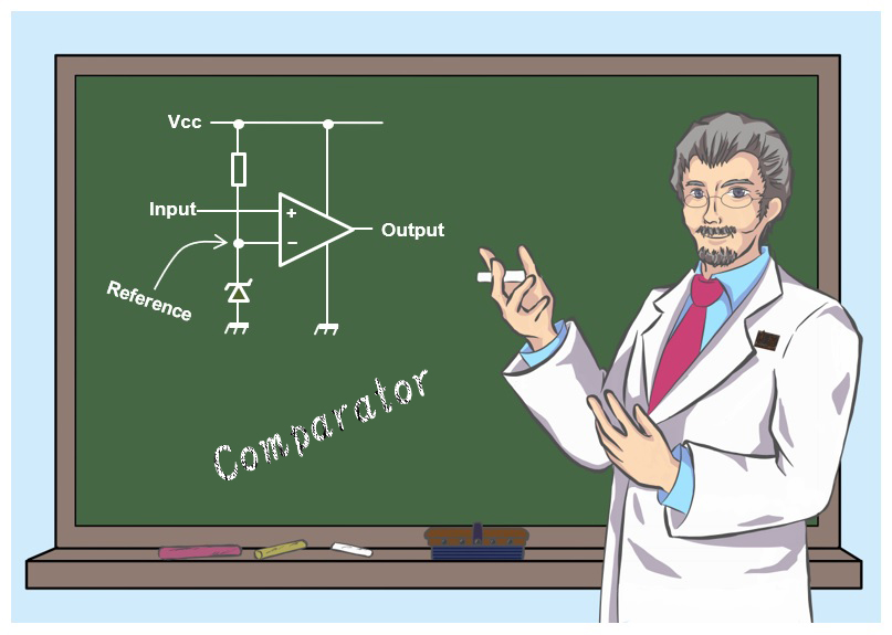
Dr. FB
For those who write computer programs, the "if, then, else” statement is a piece of cake, but it may be unfamiliar to hardware engineers who build electronic circuits. Even so, if you have done a little bit of writing in the BASIC language in the past, you might think of the “if, then, else” as a programming statement meaning "If X is True, then do Y, else (otherwise) do Z."
Comparison circuit with a comparator
Although there are differences between software and hardware, there is hardware that behaves like an “if, then, else” statement in an electronic circuit. It is a circuit that compares signal levels A and B, and operates such as if A>B, then Level = High, else level = Low. The LM358 operational amplifier was used for the comparator.
Feature of the operational amplifier
There is an article in this issue of Short Break about building an overvoltage protection device (OVP) using an LM358 single-power operational amplifier. By reading both these articles, you will have a better understanding of comparators.
The LM358 datasheet describes it as an 8-pin dual operational amplifier, with two operational amplifier circuits included in one package. The name ‘operational amplifier’ is commonly abbreviated as Op-Amp.
Op-Amps have the following major features:
(1) A very high amplification factor
(2) The amplification factor changes by the amount of negative feedback.
(3) High input impedance, and low output impedance amplifier.
(4) Amplifies the voltage difference between the (+) and (-) input terminals.
The function described in (4) above is an original function that Op-Amps have. It is well known as an amplifier that if you simply input a signal on the (+) terminal or (-) terminal, the output signal will be inverted or non-inverted.
Basic comparator function
The (+) and (-) input terminals of this Op-Amp can be used as a comparator. I think this comparator is exactly the part that follows the "if, then, else” statement" in programming.
Figure 1 shows the pin layout of the LM358. Two Op-Amps are included in one package. Each amplifier has only two input terminals and one output terminal, and there is no pin with a particularly difficult name. It is an IC chip that feels like I can use it for various things because the LM358 has only 8-pins. One amplifier has only two input terminals and one output terminal. It is easy to use it.
Pins 4 and 8 are terminals common to each amplifier for GND and DC power, respectively. Datasheets for other Op-Amps that you often see have two plus and minus power supply symbols, such as V+ and V-. Having two power inputs, such as +5V and -5V, is a bit troublesome to use for building simple electronic circuits. The LM358 can be used with a single power input, and I think it is easy to use for electronic projects.
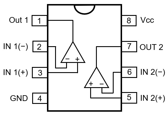
Figure 1. LM358 pin layouts
I will explain using the LM358 Op-Amp as a comparator. It is a circuit that compares two signals, and then outputs a High or a Low value if one input level becomes higher than the other input level.
As an example, 5V is applied to the IN 1(-) terminal of the amplifier as the reference value, and another signal is applied to the IN 1(+) terminal. When that signal is increased to a level that exceeds the 5V reference value, the Out 1 pin switches from Low to High.
Conversely, a reference value of 5V or higher is applied to the IN 1(-) terminal, and a signal higher than the reference value is applied to the IN 1(+) terminal. The output will switch from High to Low when the signal is reduced to below the reference value. This is the basic operation of a comparator.
Let us confirm the function of the comparator by experiments
I built a circuit as shown in Figure 2 using the LM358. This is a typical comparator circuit. It is good to solder the parts to the universal board, but for the experiment, first just place the parts on the breadboard. This makes it convenient for removing or replacing the parts later. There are two amplifier circuits included in the LM358 package, but the experiments do not use the amplifier connected to pins 5, 6, and 7.
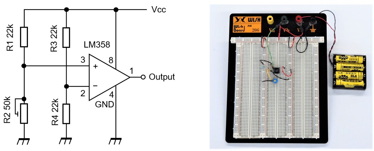
Figure 2. Circuit diagram used for the experiment and place parts on the breadboard
I determined voltages on each terminal by calculating and by actual measurement, and the values are shown in Figure 3. Connect four 1.2V rechargeable batteries in series for the power source, whose calculated value was 4.8V, but the measured value was 5.2V. Pin 8 is 5.2V because it is directly connected to the power source. Pin 2 is 2.6V, which is half of 5.2V, because the voltage of 5.2V is divided by two identical resistors. The actual measured value was 2.4V. The voltage on pin 3 is taken between a 22kΩ fixed resistor of and a 50kΩ variable resistor. When the value of the variable resistor is zero, pin 3 has the same potential as GND, so it is 0V. When the resistor is the maximum of 50kΩ, the voltage on pin 3 is taken between the 22kΩ and 50kΩ resistors so it is 3.6V in the calculation.
In other words, the voltage applied to pin 3 can be continuously adjusted between 0 and 3.6V using the variable resistor. This voltage was 0 to 3.6V in actual measurement.
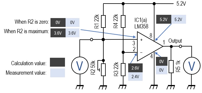
Figure 3. Voltages on each pin by calculation and actual measurement
Changes in the output on pin 1 with reference to the voltage on pin 3
As shown in Figure 4 (a) to (e), connect two multimeters to the circuit and observe the change of the input voltage on pin 3 and the change of the output voltage on pin 1 at the same time. Figure 5 is a graph showing the changes in the voltage on pins 3 and 1 by changing the resistance value of a 50kΩ variable resistor. When the voltage on pin 3 is gradually increased from 0V by adjusting the 50kΩ variable resistor, the output voltage on pin 1 suddenly increases to about 3.4V. At that time, the voltage on pin 3 was 2.6V. As you can see from the voltage display in Figure 4 (b) to (d), it seems that there is a threshold value just around 2.6V. If the voltage on pin 3 rises slightly above 2.6V, 3.4V will be output on pin 1, and if it drops below 2.6V, the output will be almost zero.
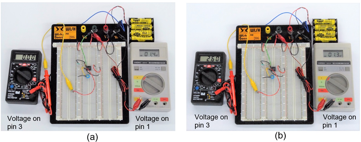
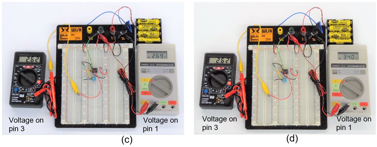
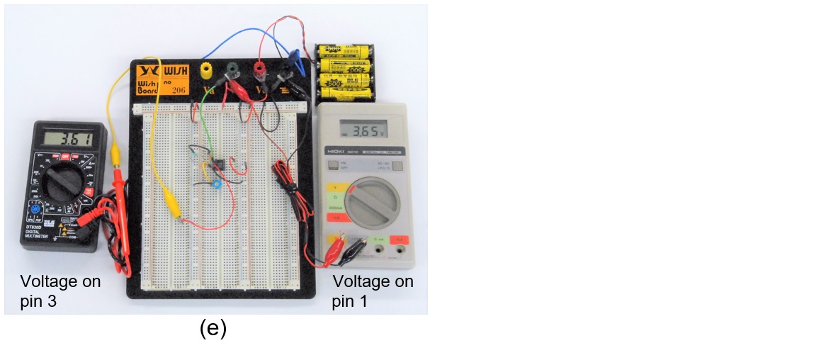
Figure 4. Connect multimeters to observe voltage changes on pin 3 and pin 1
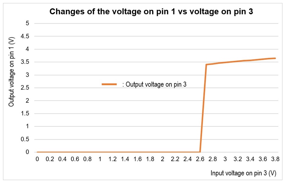
Figure 5. Input voltage on pin 3 vs output voltage characteristic on pin 1.
Summary
I conducted an experiment using the LM358 as a comparator. This time, when the voltage on pin 2 was fixed, and the voltage on pin 3 was gradually increased from zero, the voltage on pin 1 became High with the voltage just exceeding the voltage on pin 2.
On the contrary, if the voltage of pin 3 is kept constant, and the voltage on pin 2 is gradually increased from zero, the level on pin 1 was initially High, but drops from High to Low just above the voltage on pin 3. I think that various applications can be made by using the function of this comparator.
For example, if you use a CdS whose resistance value differs depending on the light instead of the resistance connected to pins 2 and 3, it is possible to switch something depending on the intensity of the light. In addition, various application examples can be considered. Please try to challenge the OP-Amp.
FB DX
Technical Trivia by Dr. FB backnumber
- Generating “Sawtooth Waves” using a D/A conversion circuit and a counter IC
- Examining a D/A converter using a Resistor Ladder
- Electronic firefly and its circuit description
- Controlling the rotation speed of a DC motor
- Description of up-down counter using 74HC192 and 74HC4511 ICs
- Considerations when making a dual voltage power supply for operational amplifiers
- Observing filter characteristics with a white noise generator
- Is noise actually reduced in twisted pair cables?
- Experiments on divider circuits using a 74HC74
- Consideration of using a photocoupler as a voltage-variable resistor
- Distorted waveform spectrum as observed on a tinySA
- Trial making of a QFH antenna
- About the inductance of coils
- Operation of analog switches
- Small digital voltmeter, 2-wire type / 3-wire type. What is the difference?
- Constant current circuit using an Op-Amp
- Coaxial cable loss to UHF and SHF
- 2.4 GHz Wireless LAN Antenna
- Let’s use MOSFETS
- 25th Comparator
- The principle of PLL
- Examination of the MLA performance
- About the Fresnel zone of the SHF band
- Level difference under open and load ends of an SSG
- Is “Made in Japan” alive? (UHF adapter again)
- Possibility experiment of passive repeater with the Back-to-Back antenna
- Why you should make SWR measurements just below the antenna!
- How reliable is the L-type BNC?
- Is the Bird 43 accurate enough?
- Does a wire dipole antenna need a balun?
- Why we don’t use a silicon diode in a crystal radio?
- How to light the 7-segment LED
- Measurement of Antenna Performance on Handheld Transceivers (Part 3)
- Measurement of Antenna SWR on Handheld transceivers (Part 2)
- Measurement of Antenna SWR on Handheld transceivers(Part 1)
- An SWR meter
- V/UHF 3-Band Antenna Dismantling Note