


Technical Trivia by Dr. FB
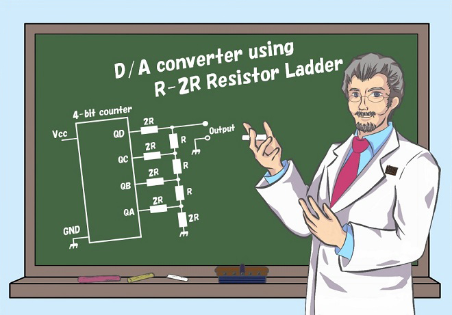
Examining a D/A converter using a Resistor Ladder
Dr. FB
Figure 1 is a conceptual diagram of a digital device. If you simply want to amplify the sound from a microphone, there is no need to process the signal with a DSP (Digital Signal Processor), but DSP processing is effective when the input sound is to be processed and output.
The AF signal from the microphone is converted to digital by an A/D (Analog/Digital) conversion circuit, the signal is processed in the DSP as needed, and then converted back to an analog signal by a D/A conversion circuit. Most digital devices process signals in a series of steps like this. In this experiment, I will test a D/A conversion circuit that can convert a 4-bit digital signal of 0000 to 1111 into an analog signal with a simple combination of resistors.
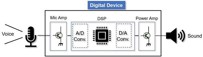
Figure 1. Conceptual diagram of digital devices
R-2R Resistor Ladder Network
Multiple resistors are sometimes combined in the form of a ladder shape and applied to a circuit as shown in the Figure 2. This combination of resistors is called a resistor ladder or resistor laddaer network because it resembles the shape of a ladder, and is used in a D/A conversion circuit that converts the "0" and "1" signals output from each bit of a digital IC into an amplitude level.
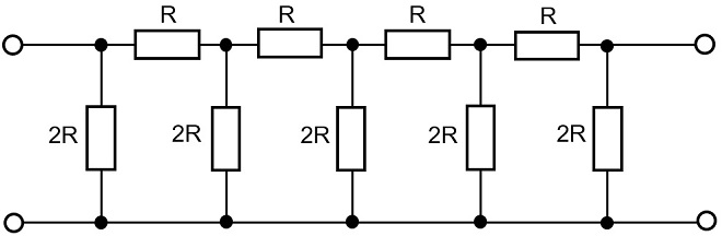
Figure 2. An example of a resitor ladder network
The resistor ladder shown in Figure 2 is constructed and connected to the 4-bit counter outputs QA to QD in the form of R1 to R8 as shown in Figure 3. The signals corresponding to the 4-bit digital signals in QA to QD appear at the outputs as changes in voltage level.
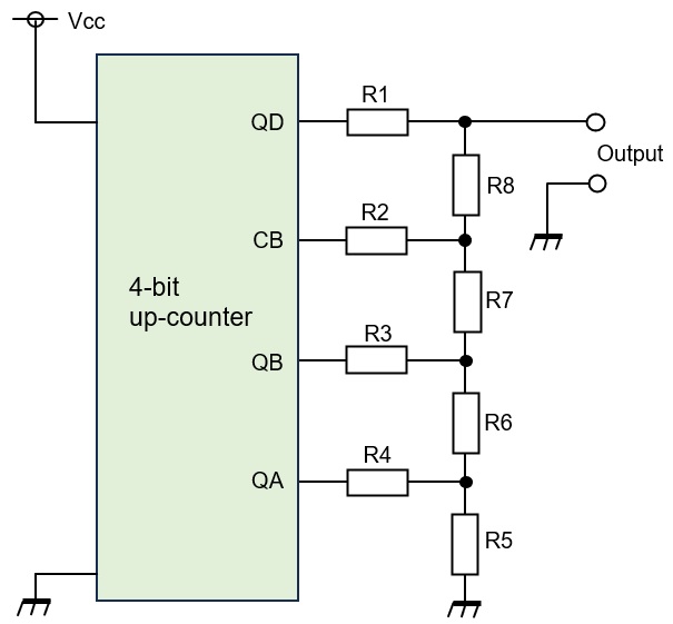
Figure 3. 4-bit D/A conversion circuit using a resistor ladder
There are rules for selecting resistor values for use in D/A conversion circuits. The resistance values of R1 to R5 should be twice the resistance values of R6 to R8. For example, if R6 to R8 are each 5 kΩ, then R1 to R5 should be twice those values, or 10 kΩ. The ratio of the resistor values is 1:2. 1 kΩ and 2 kΩ can be selected. 10 kΩ and 20 kΩ are also acceptable. The former has a low resistance value, which results in a larger current flowing in the circuit. Conversely, some literature explains that too large a resistance results in a noisy current flowing in the circuit. The resistor ladder shown in Figure 3 is sometimes called an R-2R resistor ladder network because the resistance is determined in the ratio of 1:2.
D/A conversion circuit experiment using the R-2R resistor ladder
The D/A conversion circuit shown in Figure 3 with an LED to indicate "1" is shown in Figure 4 (right). This is added to a D/A conversion circuit with 24 (=16) different signals from 0000 to 1111 made with the resistor ladder, and the output is measured with a voltmeter.
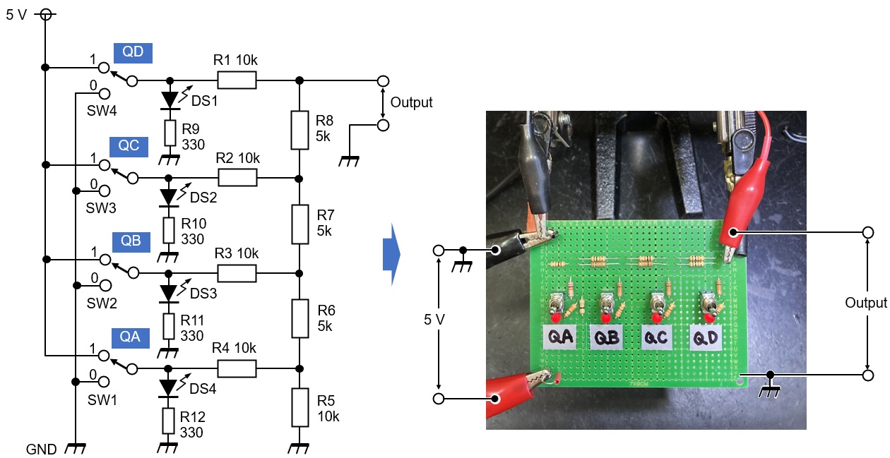
Figure 4. 4-bit D/A conversion circuit made with the resistor ladder
The table in Figure 5 shows the output voltage measured with a digital multimeter for the 4-bit signal inputs from QA to QD. The graph in Figure 5 plots the output voltage measured with a digital voltmeter, showing that changes in the numerical values of the 4 bits are expressed as changes in voltage.
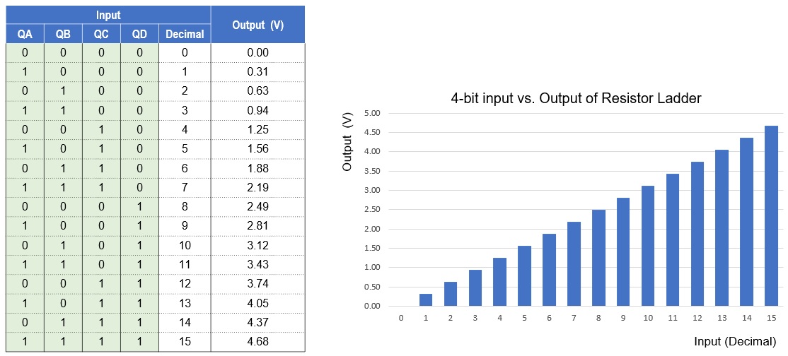
Figure 5. Input signal vs. output voltage of 4-bit R-2R resistor ladder
Summary
A 4-bit output can be expressed in 16 ways (=24) from 0000 to 1111.The lowest value is 0000 and the next is 0001. The highest value is 1111. The graph in Figure 5 shows how the output voltage V0 increases by approximately 0.313 V for each increment of this digital signal. Although the input-output characteristics appear to be linear, the output is actually a staircase-like output as shown in Figure 6.
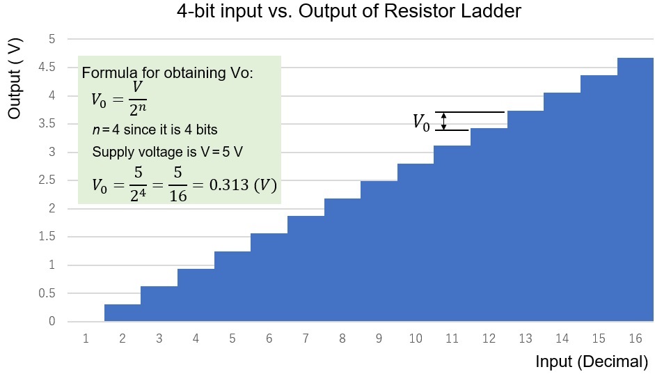
Figure 6. A 4-bit output vs analog voltage through R-2R Resistor Ladder
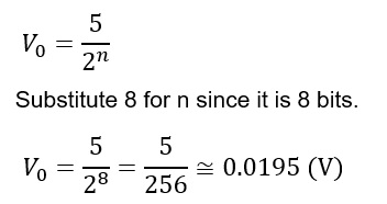
In this case, I attempted a 4-bit D/A conversion, but if this were an 8-bit conversion, the magnitude of the output voltage (V0) per step would be only 0.0195 V, as shown in the calculation below, which is smoother than a 4-bit conversion.
Application of 4-bit input counter and D/A conversion circuit
In Figure 4, the 4-bit input was done by turning switches ON and OFF. If a 4-bit up-counter IC is used instead of switches, the output of the counter starts at 0000 and ends at 1111, and the next instant the same output repeats sequentially starting at 0000 and ending at 1111 again. As a result, the signal in Figure 6 will appear continuously one after the other at the output of the resistor ladder. The signal has the shape of a sawtooth wave, as shown in Figure 7 below.
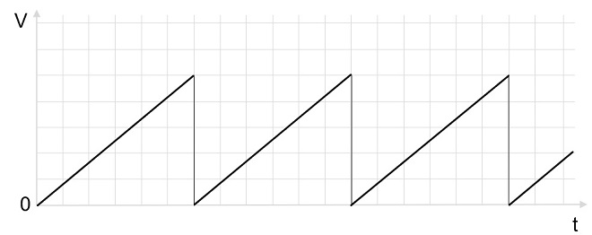
Figure 7. A sawtooth wave that can be realized with a counter and D/A conversion circuit
In the next issue, I will confirm this phenomenon with an oscilloscope.
FBDX
Technical Trivia by Dr. FB backnumber
- Generating “Sawtooth Waves” using a D/A conversion circuit and a counter IC
- Examining a D/A converter using a Resistor Ladder
- Electronic firefly and its circuit description
- Controlling the rotation speed of a DC motor
- Description of up-down counter using 74HC192 and 74HC4511 ICs
- Considerations when making a dual voltage power supply for operational amplifiers
- Observing filter characteristics with a white noise generator
- Is noise actually reduced in twisted pair cables?
- Experiments on divider circuits using a 74HC74
- Consideration of using a photocoupler as a voltage-variable resistor
- Distorted waveform spectrum as observed on a tinySA
- Trial making of a QFH antenna
- About the inductance of coils
- Operation of analog switches
- Small digital voltmeter, 2-wire type / 3-wire type. What is the difference?
- Constant current circuit using an Op-Amp
- Coaxial cable loss to UHF and SHF
- 2.4 GHz Wireless LAN Antenna
- Let’s use MOSFETS
- 25th Comparator
- The principle of PLL
- Examination of the MLA performance
- About the Fresnel zone of the SHF band
- Level difference under open and load ends of an SSG
- Is “Made in Japan” alive? (UHF adapter again)
- Possibility experiment of passive repeater with the Back-to-Back antenna
- Why you should make SWR measurements just below the antenna!
- How reliable is the L-type BNC?
- Is the Bird 43 accurate enough?
- Does a wire dipole antenna need a balun?
- Why we don’t use a silicon diode in a crystal radio?
- How to light the 7-segment LED
- Measurement of Antenna Performance on Handheld Transceivers (Part 3)
- Measurement of Antenna SWR on Handheld transceivers (Part 2)
- Measurement of Antenna SWR on Handheld transceivers(Part 1)
- An SWR meter
- V/UHF 3-Band Antenna Dismantling Note