


Technical Trivia by Dr. FB
Examination of the MLA performance

Dr. FB
About the MLA performance
An article about making a 50 MHz monoband magnetic loop antenna (MLA) is introduced in “Short Break” in this issue of FB NEWS. When I make an antenna, I am very concerned about whether it has good performance or not. Therefore, early last April, I set up a schedule with a local station to check the performance of the MLA I made, and conducted an antenna performance test. This time, I will briefly introduce the results.
By the way, we learned that “Light” waves known in daily life are one of the electromagnetic waves. The electromagnetic wave is explained in Wikipedia as waves that propagates changes in electric and magnetic fields. It can be replaced with the one in which "electric field waves" and "magnetic field waves" are alternately generated and propagated. It seems that the word "electromagnetic wave" was born from the wave of the combination of electric and magnetic fields.
The original meaning of MLA is Magnetic Loop Antenna. We know that the magnetic field induces high radio frequency (RF) current through an MLA. I have read in some books the explanation that this is different from dipole antennas, but to be honest, understanding it was difficult for me.
Performance test of an MLA
The test was conducted in Nara Prefecture in Japan at a location where the two stations are line-of-sight with each other. The environment of the two stations where the test was conducted is shown in the table below.
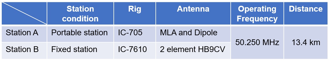
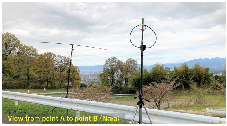
Figure 1. Two types of antennas used by station A in the test
(Left is a Buddipole® dipole, right is a home-made MLA)
(1) Comparison as a receive antenna
Station B transmitted an unmodulated single signal (carrier) and Station A received the signal with the MLA and a full-sized dipole. I observed the signal strength received on each antenna with the S-meter of an IC-705. As mentioned at the beginning, MLA is the antenna introduced in the “Short Break”” section. The dipole is a Buddipole® dipole. Figure 1 shows the test environment of Station A.
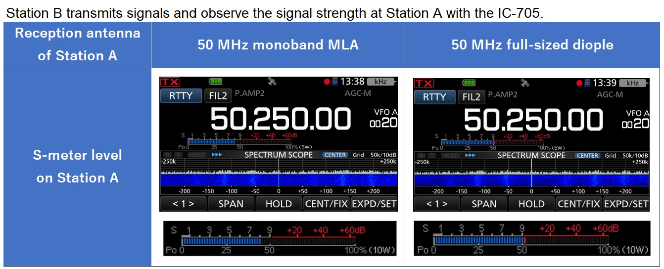
Figure 2. S-meter display of signals received at Station A with the MLA and the dipole, respectively.
The signal strength received using the MLA was S8, as you can see in Figure 2 above. The signal strength received using the dipole instead of the MLA was S9 + 1. There was a difference between them, but the difference was not as much as I expected.
(2) Comparison as a transmit antenna
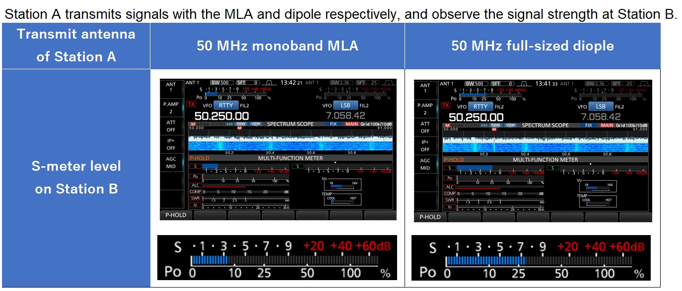
Figure 3. S-meter display at Station B when Station A transmitted with the MLA and the dipole, respectively.
The MLA and dipole were connected to the IC-705 of Station A, which transmitted a carrier signal using each antenna. Station B received the signal, and displayed the signal strength on the S-meter of the IC-7610. As a result shown in Figure 3, when transmitting with the MLA, the S-meter displayed S3 + 1, and when transmitting with the dipole, it showed S7 + 1. There was a difference of S4 on the S-meter scale.
(3) What I noticed during the test
Before tests 1 and 2 above, I connected the MLA to the IC-705 of Station A to briefly confirm the performance. Figures 4 (a) and 4 (b) are screen captures of the waterfall and S-meter display when the respective antennas were connected. This is not the signal of some stations, but the display when the antenna is just connected.
When the dipole is connected, the S-meter showed about 1.5 to 2 as shown in Figure 4 (a). On the other hand, when the MLA is connected, it showed up to the S3 + 1 scale as shown in Figure 4 (b). And you can see, some unwanted signals were received in the waterfall display about every 50 kHz.
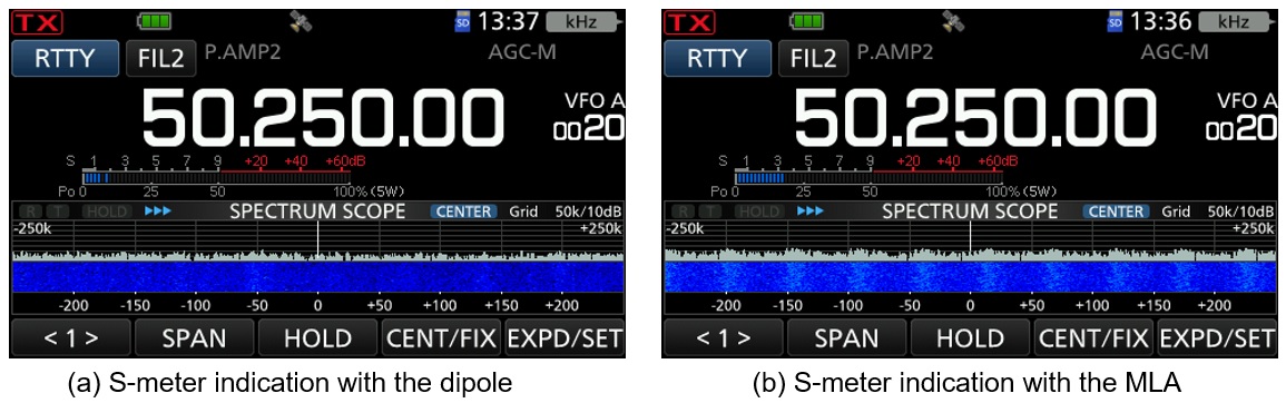
Figure 4. S-meter display when the MLA and dipole are connected respectively.
Summary of experimental results
Immediately after starting the tests, I felt the difference between MLA and dipole without looking at the experimental results. In a word, the MLA has a reasonably satisfactory performance for reception, but transmission is not as good as expected. If reception was good, I thought that transmission would perform reasonably well, but it wasn't "the reverse is also true."
Since one wavelength of 50 MHz is contained in a loop length of a little over 1 meter circumference, some losses cannot be denied. Still, reception was beyond my imagination. The magnetic field wave mentioned earlier may be a factor, but this theory is not well understood and is still speculative.
As proof of the result, the photograph shown in Figure 2 shows that the S-meter displayed S8 and S9 + 1 scale when the MLA and the diople were connected respectively. The difference is approximately 1 on the S-meter. On the other hand, Figure 3 shows the deflection of the S-meter of Station B when transmitting from Station A. When Station A transmitted using the MLA, Station B received the signal with a little over S3, but with a dipole it received at a little over S7. It's a simple calculation, but the difference is as much as 4 on the S-meter.
Summary of MLA performance
Pros of the MLA are:
・ Lightweight
・ Compact
・ Simple structure
・ It is reasonably good as a receiving antenna
Cons, if improved will it a very good antenna:
・ Passband is very narrow (High-Q)
・ It is difficult to have a pin-point tuning because of the high-Q.
・ Adjustment shifts off when the human body approaches the antenna
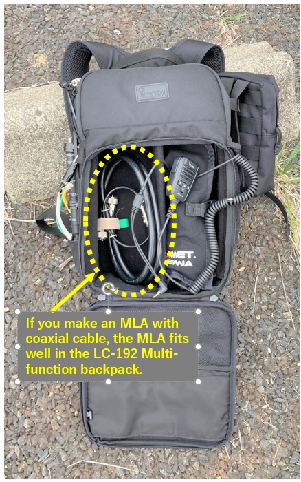
Figure 5. MLA fits compactly in the LC-192.
Impressions using the MLA
The MLA making article introduced in this issue, Short Break, is intended for amateur radio operators who do half-mountain hiking and half-radio operation. I think that the MLA is good antenna, based on the testing done above. If you are going outdoors to concentrate on only radio operation, you will need a beam antenna. It's nice to be able to take a beam antenna if you go outdoors or to the top of a mountain by car, but it's a little difficult for people who are not in top condition to hike up the mountain and bring a large beam antenna. The MLA, though a little cirtical to adjust, is easy to carry when you're hiking in the mountains and easy to asssemble when you take a break at a scenic location.
In these tests, the transmission efficiency of the MLA did not seem to be good, but when you transmit from the top of a high mountain, you should be able to communicate with distant places by taking advantage of the mountain’s high elevation.
The antenna is not that difficult to make it. I thought it would be an antenna that I would definitely recommend for hams who enjoy half-radio operation and half-mountain hiking. FBDX
References:
Denpasha HAMworld November 2019 issue, January 2020 issue, March 2020 issue, May 2020 issue "From the encounter with the electromagnetic field antenna to today"
CQ Publishing Co., Ltd. CQ ham radio Separate Volume QEX No.25 Introductory Making and Learning MLA
Wikipedia "Electromagnetic waves
Technical Trivia by Dr. FB backnumber
- Generating “Sawtooth Waves” using a D/A conversion circuit and a counter IC
- Examining a D/A converter using a Resistor Ladder
- Electronic firefly and its circuit description
- Controlling the rotation speed of a DC motor
- Description of up-down counter using 74HC192 and 74HC4511 ICs
- Considerations when making a dual voltage power supply for operational amplifiers
- Observing filter characteristics with a white noise generator
- Is noise actually reduced in twisted pair cables?
- Experiments on divider circuits using a 74HC74
- Consideration of using a photocoupler as a voltage-variable resistor
- Distorted waveform spectrum as observed on a tinySA
- Trial making of a QFH antenna
- About the inductance of coils
- Operation of analog switches
- Small digital voltmeter, 2-wire type / 3-wire type. What is the difference?
- Constant current circuit using an Op-Amp
- Coaxial cable loss to UHF and SHF
- 2.4 GHz Wireless LAN Antenna
- Let’s use MOSFETS
- 25th Comparator
- The principle of PLL
- Examination of the MLA performance
- About the Fresnel zone of the SHF band
- Level difference under open and load ends of an SSG
- Is “Made in Japan” alive? (UHF adapter again)
- Possibility experiment of passive repeater with the Back-to-Back antenna
- Why you should make SWR measurements just below the antenna!
- How reliable is the L-type BNC?
- Is the Bird 43 accurate enough?
- Does a wire dipole antenna need a balun?
- Why we don’t use a silicon diode in a crystal radio?
- How to light the 7-segment LED
- Measurement of Antenna Performance on Handheld Transceivers (Part 3)
- Measurement of Antenna SWR on Handheld transceivers (Part 2)
- Measurement of Antenna SWR on Handheld transceivers(Part 1)
- An SWR meter
- V/UHF 3-Band Antenna Dismantling Note