


Technical Trivia by Dr. FB
Considerations when making a dual voltage power supply for operational amplifiers
Dr. FB
Many of our amateur radios require DC power. Normally, we connect a two-wire red and black DC cable from a DC power supply or battery to a radio to provide DC power. However, there are some complicated power supplies in the electronics world. For example, there are positive (+6 V) and negative (-6 V) power supplies for certain needs. Then, where are the +6 V (positive 6 V) and -6 V (negative 6 V) power supplies used? Some elements will not operate unless both positive and negative voltages are applied.
Operational amplifiers requires both positive and negative power for operation
The operational amplifier itself, which often appears in the FB News' electronic projects, requires both a positive and a negative voltage. Let us call the power source a Dual voltage supply, as opposed to a Single voltage supply. Figure 1 shows the pin layout of the NJM4558D, which requires dual voltages.
As you can see in Figure 1, for the pin allocations of the NJM4558D, pin 4 is labeled “-Vcc” and pin 8 is labeled “+Vcc.” This means that a virtual ground (GND) is set, -6 V is applied to pin 4 and +6 V is applied to pin 8, with virtual GND as the reference point.
A typical constant-voltage power supply has two terminals, red and black, where red is positive and black is negative, and the voltage on the red terminal is set with respect to the black terminal. Since the output of this popular constant-voltage power supply is only a positive voltage, even if that positive voltage is added to the +Vcc of the operational amplifier, there is no negative -Vcc voltage applied, so the amp will not operate.
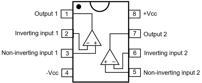
Figure 1. NJM4558D pin allocations
In most of the electronic circuits introduced in the FB News so far, operational amplifiers are operated by batteries or ordinary single voltage power supplies, not special power supplies. Although I have explained that both positive and negative power supplies are required for operational amplifiers, there is actually a way to operate an operational amplifier with a single voltage source.
(1) Use an operational amplifier that operates with a single voltage. (Figure 2)
Operational amplifiers basically operate with both positive and negative voltages, but there are some that operate with only a single positive voltage applied. Although their operation is inferior to that of operational amplifiers that are supplied with both positive and negative voltages, they are useful for circuits that can still operate without problems.
(2) Add an additional circuit that can be regarded as a dual voltage supply.
Even an operational amplifier that requires both positive and negative voltages, such as the one shown in Figure 1, can be powered by only a positive voltage supply, with the additional circuit that looks like it is adding both positive and negative voltages.
(3) Build an independent dual voltage supply for positive and negative voltages.
Build an independent dual power supply circuit and supply positive and negative voltages from that circuit to the operational amplifier. It is simple in principle, but it requires a lot of work. In this issue, I will explain this positive and negative dual power supply, which is useful for operational amplifier experiments.
Figure 2 shows the pin assignment diagram of the LM358, a general-purpose operational amplifier that operates on a single supply voltage. The pin assignment is identical to that of the operational amplifier shown in Figure. 1, except for the yellow pins 4 and 8, which have different specifications. The pin assignments are all the same. It seems that the constant-voltage power supply that we usually use is sufficient for the power supply connection.
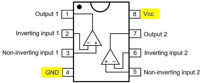
Figure 2. Operational amplifier that operates with a single voltage
If it would be better to have all operational amplifiers operate with a single voltage from the beginning, but by adding a positive and negative voltage, we can see performance that can only be achieved with both voltages.
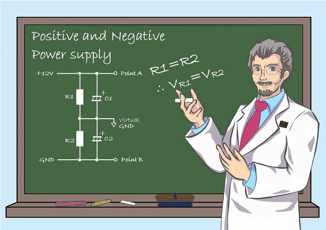
Two resistors to build a + 6 V and - 6 V voltage source
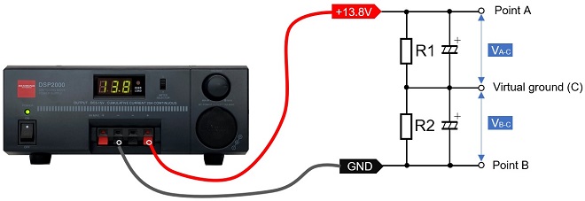
Figure 3. Voltage divider circuit using two resistors
A circuit made with two resistors is shown in Figure 3 above. Let the resistor values be R1 = R2; R1 and R2 can be 1 Ω or 10 kΩ, or any other value. Place a black probe at the midpoint (C) and a red probe at point A, and measure the voltage between A and C. VA-C = 6.9 V is displayed, which is one-half of 13.8 V. Next, leaving the black probe in the place and put the red probe on point B. A digital voltmeter reads VB-C = - 6.9 V. Two resistors can be used to make both positive and negative power supplies of ± 6.9 V. On an analog multimeter with a pointer that indicates the values read on a scale, the pointer can swing all the way to the left, but only for a moment; the meter will break.
With no load connected between A and C, and B and C, the same voltage appears at VA-C and VB-C, but when different loads are connected, VA-C and VB-C will produce different voltages. This circuit can be used if the loads connected to the output are the same, or approximately the same load. Unfortunately it does not work with very different loads connected, as the circuit outputs different voltages.
How to run operational amplifiers with a single voltage source
The circuit below is taken from an article on operational amplifiers in the November 2021 issue of the monthly FB NEWS. These are principal circuits for a non-inverting circuit and an inverting circuit, using both positive and negative DC voltages.
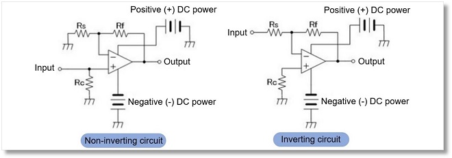
Figure 4. Principle diagrams of non-inverting and inverting circuits using separate positive and negative DC power supplies. Note: Quoted from the URL https://www.fbnews.jp/202111/junkshop/
Many operational amplifiers are used in transceivers we own. Operational amplifiers basically operate with a dual supply voltages, as explained earlier. The operation regards the single supply voltage as one with dual voltages. A "deemed operation circuit" is incorporated.
For example, one way to use an inverting amplifier with a single voltage is to use another potential as the zero point when applying the positive voltage, instead of using the ground (GND) of the power supply as the zero point. By changing the reference point of operation, a single voltage is regarded as dual voltages.
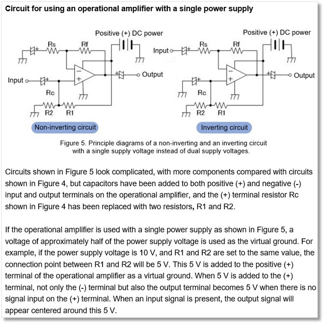
Figure 5. Principle diagrams of a non-inverting and an inverting circuit with a single supply voltage instead of dual supply voltages. Note: Quoted from the URL https://www.fbnews.jp/202111/junkshop/
Circuits shown in Figure 5 look complicated, with more components compared with circuits shown in Figure 4, but capacitors have been added to both positive (+) and negative (-) input and output terminals on the operational amplifier, and the (+) terminal resistor Rc shown in Figure 4 has been replaced with two resistors, R1 and R2.
If the operational amplifier is used with a single power supply as shown in Figure 5, a voltage of approximately half of the power supply voltage is used as the virtual ground. For example, if the power supply voltage is 10 V, and R1 and R2 are set to the same value, the connection point between R1 and R2 will be 5 V. This 5 V is added to the positive (+) terminal of the operational amplifier as a virtual ground. When 5 V is added to the (+) terminal, not only the (-) terminal but also the output terminal becomes 5 V when there is no signal input on the (+) terminal. When an input signal is present, the output signal will appear centered around this 5 V.
Operation of operational amplifier single voltages are useful when negative supply voltages are not available. Furthermore, certain applications using high voltages, and high current operational amplifiers can derive important benefits from single voltage operation.
How to use a three-terminal regulator for dual supply voltages
There is an IC with a constant voltage circuit called a three-terminal regulator. The IC has three terminals and is an electronic component that can easily be configured as a constant voltage circuit. There are two types of three-terminal regulators: the 78L05 series, which inputs a positive voltage and outputs a positive voltage, and the 79L05 series, which inputs a negative voltage and outputs a negative voltage.
Successfully combining these two types of positive and negative three-terminal regulators is shown in Figure 6 (Right). Positive and negative voltages can be created with respect to the virtual ground. A current of more than 100 mA can also be obtained with three-terminal regulators.
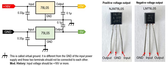
Figure 6. Dual supply voltage using 78L05 and 79L05 series three-terminal regulators
The manufacturer's data sheet provides a circuit that combines a 78L05 (Positive voltage regulator) and a 79L05 (Negative voltage regulator) as an application example to create a dual voltage circuit, as shown in Figure 6. It is important to note that the 78L05 and 79L05 series ICs have similar packages, but the lead wire assignments are different.
How to combine a comparator with a push-pull circuit
Now, the main purpose of this project is the circuit described here. Although it is not likely to be used in such a way that both positive and negative voltages are varied each time, it is sometimes necessary to observe changes in the supply voltages and output signals in circuits used for experiments. Figure 7 shows the power supply circuit that can vary the output voltage of both positive and negative power supplies as dual voltages. It is useful to have one of these circuits for experiments.
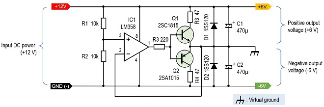
Figure 7. Positive and negative power supplies with comparator and push-pull circuit
A comparator (IC1) is used to control the circuit. IC1 itself is an LM358 general-purpose operational amplifier that operates on a single voltage. This operational amplifier functions as a comparator. A push-pull transistor circuit is connected to the output of the comparator so that a current can be drawn, depending on the transistor specifications. The Q1 and Q2 transistors used here are NPN and PNP, but we need to use complementary transistors that have the same characteristics. Here, for reasons of transistors on hand, I used a 2SC1815 for Q1 and a 2SA1015 for Q2, since the maximum current that can flow through these transistors is about 150 mA and I used 47 Ω for R3 and R4, respectively.
I used a regulated DC power supply, and 6 V was added to pin 3 of IC1, which is the input voltage of 12 V divided by 10 kΩ and 10 kΩ. If the voltage input to pin 3 is V3 and the voltage input to pin 2 is V2, the voltage output from pin 1, V1, is as follows.
- When V3-V2 = positive value (higher than 0 V), V1 outputs Vcc level.
- When V3-V2 = negative value (lower than 0 V), V1 outputs 0 V(GND level).
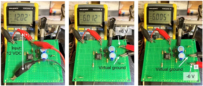
Figure 8. The circuit in Figure 6 is being tested on a universal PCB.
How to use a commercially available DC-DC converter
I found a DC-DC converter at a parts store that does not allow variable output voltage but can provide a reasonable current. The price was approximately 4 US dollar per piece. Even if I were to make it myself, I think it would be a bit impossible to make it at this cost. The output voltage of this unit is constant, even when the input voltage changes. It seemed to be ideal for a dual supply voltage for operational amplifiers. The circuit is a DC-DC converter, so the unit radiates noise.
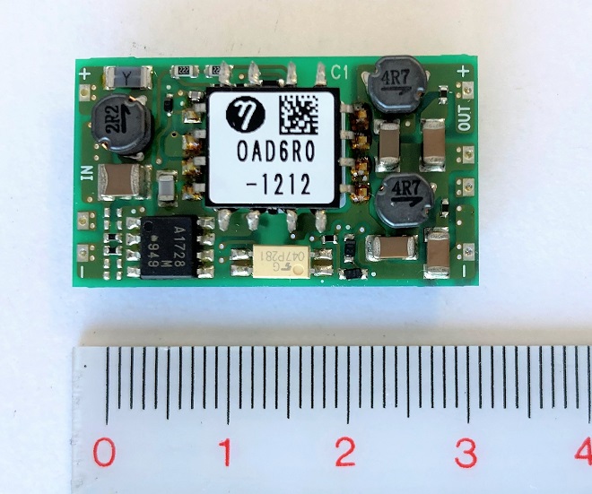
Figure 9. Commercial DC-DC converter Input: DC 9 to 18 V Output: ±12 V (0.25 A)
Summary
In the two-resistor circuit shown in Figure 3 above, I explained that the size of each load connected to the positive or negative voltage has a significant effect on the output voltage. The use of a three-terminal regulator, the circuit shown in Figure 7, or the DC-DC converter shown in Figure 8 eliminates this concern. It is advisable to use the appropriate method according to the application.
Reference information
Figures 4 and 5 in the text are taken from the following URL, courtesy of the author. The original text is written in Japanese, but has been translated into English by the the monthly FB NEWS editorial team.
November 2021 on the monthly FB NEWS
FBDX
Technical Trivia by Dr. FB backnumber
- Generating “Sawtooth Waves” using a D/A conversion circuit and a counter IC
- Examining a D/A converter using a Resistor Ladder
- Electronic firefly and its circuit description
- Controlling the rotation speed of a DC motor
- Description of up-down counter using 74HC192 and 74HC4511 ICs
- Considerations when making a dual voltage power supply for operational amplifiers
- Observing filter characteristics with a white noise generator
- Is noise actually reduced in twisted pair cables?
- Experiments on divider circuits using a 74HC74
- Consideration of using a photocoupler as a voltage-variable resistor
- Distorted waveform spectrum as observed on a tinySA
- Trial making of a QFH antenna
- About the inductance of coils
- Operation of analog switches
- Small digital voltmeter, 2-wire type / 3-wire type. What is the difference?
- Constant current circuit using an Op-Amp
- Coaxial cable loss to UHF and SHF
- 2.4 GHz Wireless LAN Antenna
- Let’s use MOSFETS
- 25th Comparator
- The principle of PLL
- Examination of the MLA performance
- About the Fresnel zone of the SHF band
- Level difference under open and load ends of an SSG
- Is “Made in Japan” alive? (UHF adapter again)
- Possibility experiment of passive repeater with the Back-to-Back antenna
- Why you should make SWR measurements just below the antenna!
- How reliable is the L-type BNC?
- Is the Bird 43 accurate enough?
- Does a wire dipole antenna need a balun?
- Why we don’t use a silicon diode in a crystal radio?
- How to light the 7-segment LED
- Measurement of Antenna Performance on Handheld Transceivers (Part 3)
- Measurement of Antenna SWR on Handheld transceivers (Part 2)
- Measurement of Antenna SWR on Handheld transceivers(Part 1)
- An SWR meter
- V/UHF 3-Band Antenna Dismantling Note