


Technical Trivia by Dr. FB
Operation of analog switches

Dr. FB
When most people think of a switch, they think of the ones shown in Figure 1. They are very simple to use. The wiring needs to be soldered, but the switch is turned ON and OFF by moving a lever or pushing a button. The switch opens and closes the circuit by the physical contact and separation of the metal contacts inside. In this article, I will explain semiconductor switches, commonly known as ŌĆ£Analog switches,ŌĆØ rather than mechanical switches. As there is no mechanical parts, there is no contact failure and no chattering phenomena. They can be used for a wide range of applications by switching circuits ON and OFF electrically.
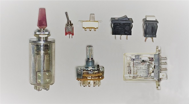
Figure 1. Mechanical switches
Switching action with MOSFETs
Bipolar transistors, FETs and diodes are electronic components that switch circuits ON and OFF using semiconductors. Unlike mechanical switches, these components are switched ON and OFF by applying a high (H) or a low (L) voltage as a control signal to create a low or high impedance between two terminals in the semiconductor, which is the function of the switch. These switches made of semiconductors are generally called analog switches. In this article, I will focus on MOSFET-based analog switch ICs.
In a previous article in the Short Break section of this web magazine, "Building an automatic backup power switching unit," I discussed the switching behavior of MOSFETs, which are the source of analog switches. I also explained the operation of analog switches in the Technical trivia by Dr. FB in the same way in the article "LetŌĆÖs use MOSFEs."
Semiconductor switching is of course possible with general-purpose bipolar transistors, but here I will consider an analog switch based on a MOSFET circuit, which is suitable for switching. By applying an H or a L control signal to the gate, the MOSFET could be made to conduct (low impedance) or not conduct (high impedance). Figure 2 shows an example of this circuit, which is the basis of the analog switch. In "Building an automatic backup power switching unit," when the voltage applied to the gate changes to zero, the MOSFET becomes conductive between its source and drain, as if it were a mechanical switch that is turned ON.
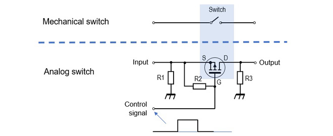
Figure 2. Principle of an analog switch
The mechanical switches shown in Figure 1 are switched ON and OFF by manually moving the switch lever or button. In the case of analog switches, the ON/OFF action is carried out by a control signal. This is like an ŌĆ£If statementŌĆØ in a computer program. If the control signal is L, then the source-drain connection becomes conductive, or vice versa. Figure 3 summarizes these state changes.
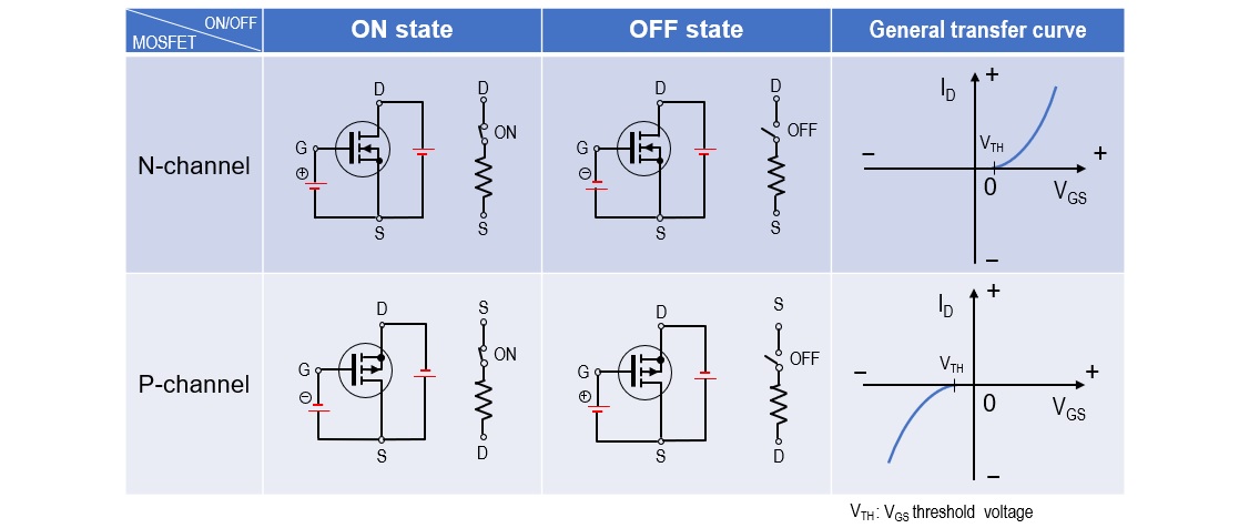
Figure 3. Change in state of N-channel and P-channel MOSFETs
4066 Analog switch
In addition to MOSFETs, the switching circuit shown in Figure 2 requires resistors R1, R2 and R3, which need to be integrated into the circuit board to make the circuit work. The analog switch IC I describe has only three terminals - input, output, and control signal - to make it easy to use.
In the connection of a mechanical switch, there is no distinction between the hot and cold side connections of the circuit, but the circuit shown in Figure 3 will not work if you accidentally connect leads of the source and drain in reverse. However, the analog switch IC shown in Figure 4 can be used like a mechanical switch, regardless of lead direction. The part number of the IC used in this project is TC74HC4066AP (hereafter called 4066), and according to the data sheet of the manufacturer it is described as a Quad Bilateral Switch. If you search the internet for analog switches, you will find many other ICs.

Figure 4. Function table for the 4066 analog switch
Figure 5 left shows the appearance of the IC chip. There are other types of ICs available, but I will use the dip type, which is more convenient for my experiments this time. Figure 5 (right) is a diagram of the connection of each pin. You can understand the operation by drawing the terminals of each analog switch with an equivalent circuit, as shown. In the case of an ordinary mechanical switch, when the switch is turned ON, it becomes conductive and the resistance between two terminals is almost zero ohms. According to the data sheet of the 4066 (Figure 6), the ON-resistance is 50 ╬® when Vcc is 9 V. Therefore, the resistance of 50 ╬® may not be negligible in a circuit that turns a small current ON or OFF. In any case, 50 ╬® is not a problem for logic circuits and switching circuits.
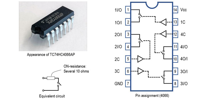
Figure 5. 4066 appearance and pin connection diagram
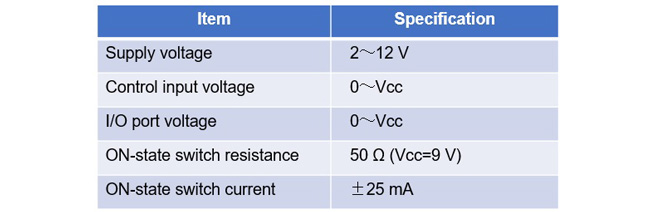
Figure 6. 4066 ratings (taken from TC74HC4066AP datasheet)
Application (Part 1)
Let us use an analog switch to light up an LED, although there is no particular need to use an analog switch if all I want to do is light up an LED, I will dare to experiment with it this time by seeing how it works. The blue broken line in the circuit diagram (Figure 7) shows how the mechanical switch is used to turn ON the LED. It is very simple: close the switch and the LED lights up.
The right side of Figure 7 shows the circuit for lighting the LED using an analog switch. It is much more complicated than the circuit using mechanical switches, but the switching in the lighting section is the same as for mechanical switches. The 4066 contains four analog switches in one package, but only one is used in this experiment. The analog switch is switched ON or OFF in this circuit using a mechanical switch to apply an H or an L signal to pin 13 (the control signal), but in a real application the output of the logic can be added to pin 13 to electrically switch the LED ON or OFF, depending on the operation of the circuit. This is where analog switches become convenient.
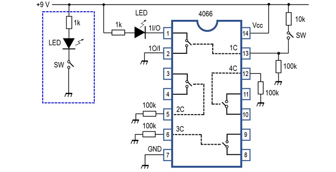
Figure 7. Experiment with an analog switch IC to turn ON an LED
The input terminals of the control signals not used in the 4066 used here are connected to Vcc or GND. In the circuit shown in Figure 7, they are connected to GND through a 100 k╬® resistor. If the device is left floating with no connection to either Vcc or GND, the internal semiconductor switch will be switched on halfway and the 4066 will faintly light up the LED. This is noted in the datasheet as a note.
Application (Part 2)
The 4066 can be used to build a 4-input AND circuit. The 4066 package contains 4 analog switches, which are all connected in series, as shown in figure 8, so that unless the outputs of logic circuits (1) to (4) are all high, no voltage is applied to the base of the transistor and the relay does not work.
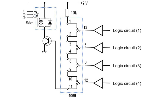
Figure 8. AND circuit with 4 inputs using analog switches
Reference
While the two applications shown above were DC switching only, analog switches are also capable of switching at the high frequencies we work with. I have not experimented with the high frequencies, but the datasheet states that when the input signal level is adjusted so that the output is 0 dBm and the output is 3 dB lower than that, the typical frequency is 200 MHz. I will experiment with this at some point and report back here.
FBDX
Technical Trivia by Dr. FBŃĆĆbacknumber
- Generating ŌĆ£Sawtooth WavesŌĆØ using a D/A conversion circuit and a counter IC
- Examining a D/A converter using a Resistor Ladder
- Electronic firefly and its circuit description
- Controlling the rotation speed of a DC motor
- Description of up-down counter using 74HC192 and 74HC4511 ICs
- Considerations when making a dual voltage power supply for operational amplifiers
- Observing filter characteristics with a white noise generator
- Is noise actually reduced in twisted pair cables?
- Experiments on divider circuits using a 74HC74
- Consideration of using a photocoupler as a voltage-variable resistor
- Distorted waveform spectrum as observed on a tinySA
- Trial making of a QFH antenna
- About the inductance of coils
- Operation of analog switches
- Small digital voltmeter, 2-wire type / 3-wire type. What is the difference?
- Constant current circuit using an Op-Amp
- Coaxial cable loss to UHF and SHF
- 2.4 GHz Wireless LAN Antenna
- Let’s use MOSFETS
- 25th Comparator
- The principle of PLL
- Examination of the MLA performance
- About the Fresnel zone of the SHF band
- Level difference under open and load ends of an SSG
- Is “Made in Japan” alive? (UHF adapter again)
- Possibility experiment of passive repeater with the Back-to-Back antenna
- Why you should make SWR measurements just below the antenna!
- How reliable is the L-type BNC?
- Is the Bird 43 accurate enough?
- Does a wire dipole antenna need a balun?
- Why we donŌĆÖt use a silicon diode in a crystal radio?
- How to light the 7-segment LED
- Measurement of Antenna Performance on Handheld Transceivers (Part 3)
- Measurement of Antenna SWR on Handheld transceivers (Part 2)
- Measurement of Antenna SWR on Handheld transceivers(Part 1)
- An SWR meter
- V/UHF 3-Band Antenna Dismantling Note