


Technical Trivia by Dr. FB
An SWR meter

Dr. FB
Nipponbashi in Osaka, an electronic goods shopping area like Akihabara in Tokyo. I found a retro-style power meter at an amateur radio shop. It seemed that SWR can also be measured. Only the name "ham” is printed on the front panel, so it is not clear who made it. About 50 years ago, there was a company called ASAHI SEIKO in Japan, which is very similar model to the ME-IIB that was sold. I didn't know if it would work, but I decided to buy it anyway. I asked the owner, "How much is it?" But he said, "It's very old and I’m not sure that it works, so you don't need to pay any money." The point is, "Take it." I said that I would gladly pay, but he said it wasn’t necessary. I said “Ummm…” Finally, I decided to accept his offer.
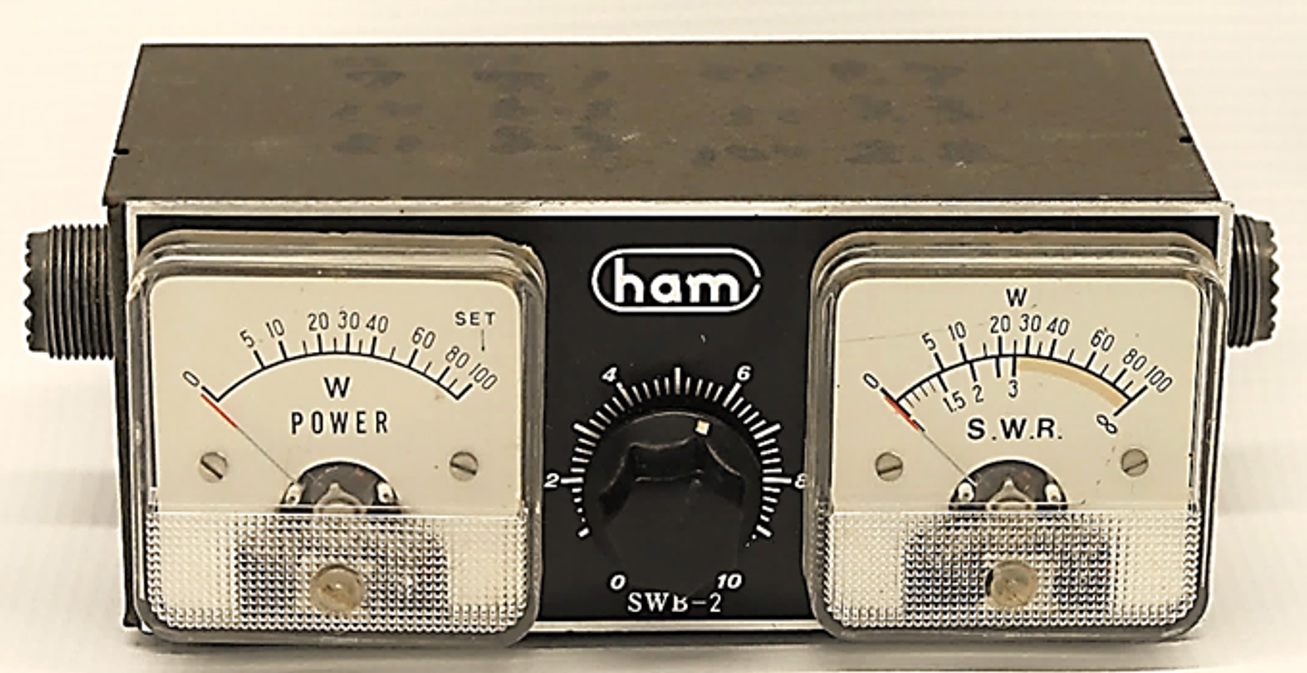
Figure 1. The retro-style power meter
1. Two types of power meters
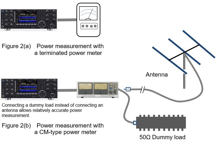
There are two main types of power meters. One is a terminated power meter, and the other is a through-line power meter. It is also called CM-type* power meter. Hereafter, I use the name “CM-type power meter.” The terminated type is used for accurate output measurement of transmitters and RF amplifiers, and the CM-type power meter is used for measuring forwarding (traveling) wave power and reflected wave power, and is inserted between the transmitter (or transceiver) and antenna. There is also a separate type of power meter that can measure relatively small RF power with high accuracy, but it is mainly used in research and development, so it will not be discussed here because it is not commonly used by amateur radio operators.
* See “4. About CM coupling” for details.
The terminated power meter has a non-inductive resistor whose resistance does not change value with frequency in the meter as a load. A small part of the power consumed by the load resistor is extracted, detected, and the power is indicated on the meter. In some cases, high frequency power is consumed by a thermocouple instead of a resistor, and the power consumption of the Joule heat is measured by the meter. To measure power with a terminated type power meter, the transmitter or transceiver is connected directly to the power meter, so the power cannot be measured during a QSO.
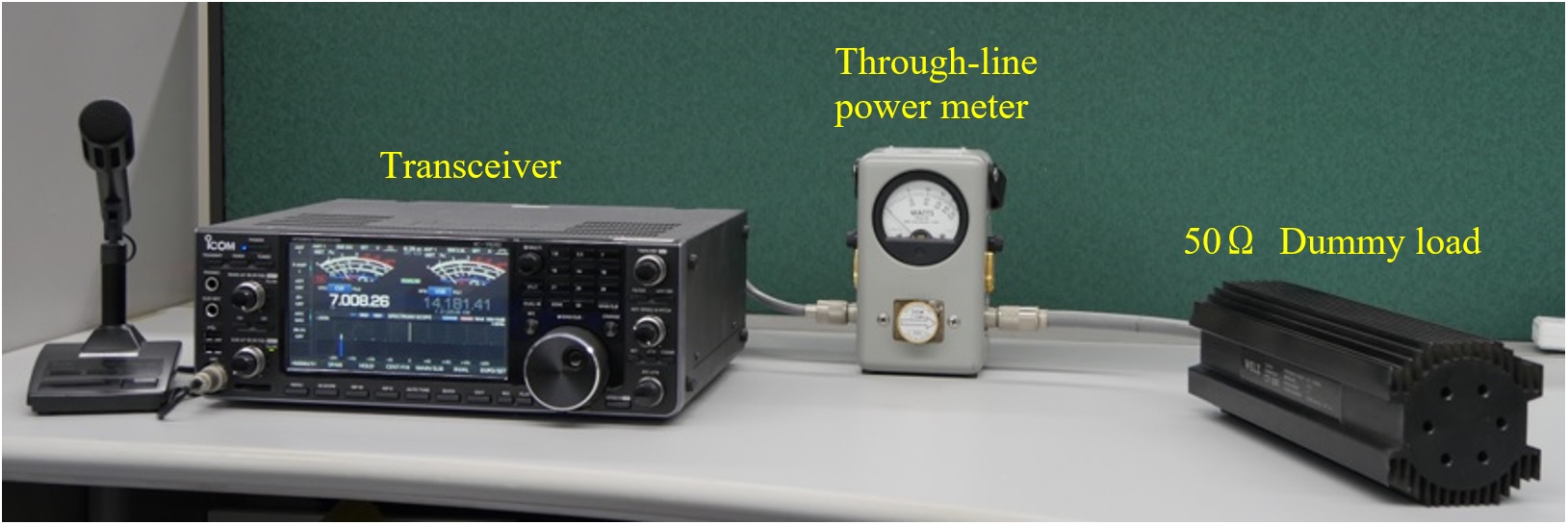
On the other hand, a CM-type power meter can measure the transmitted power while being QSO. Also, by connecting the meter between the transmitter and the antenna, the forwarding wave power supplied from the transmitter to the antenna and the reflected wave power returning from the antenna to the transmitter can be measured simultaneously. It is important to understand that the power meter reading with a CM-type power meter is not as accurate as a terminated power meter. This is because the antenna corresponding to the load is not necessarily a pure resistance of 50 Ω. As shown in the photo at the beginning, even a CM-type power meter can measure relatively accurate power by connecting to a 50 Ω dummy load.
2. Principle of a CM-type power meter
I disassembled the meter brought back from the Nipponbashi store. Figures 3 (a) to (c) show the internal views of the meter.
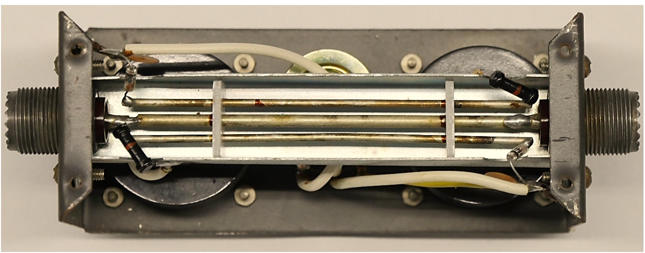
Figure 3(a) Structure where the power of the CM-type power meter passes
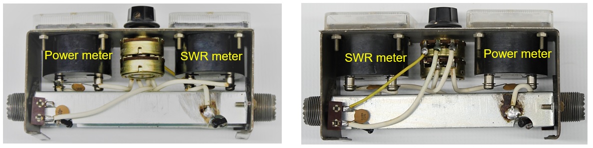
Figure 3(b) Top view, Figure 3(c) Bottom view
Figure 3(a) shows that three conductors are installed inside. The thick conductor at the center is connected to the center of the SO239 connector that connects to the transmitter and the antenna. You can also see the two conductors arranged in parallel on both sides of this center conductor. These two conductors are called pickup lines and electrically form a directional coupler, with the center conductor through a C (Capacitive coupling) and M (Mutual inductive coupling).
When RF power passes through the center conductor, minute RF power is also induced in the pickup lines on both sides due to the CM coupling. The voltage for the forwarding wave power and the voltage for the reflected wave power induced by these pickup lines (two conductors) are detected by diodes, respectively, and the voltage is swung by a meter so that the power (W) and SWR can be known.
3. SWR measurement
In the circuit diagram shown in Figure 4 below, a voltage for the forwarding wave power is induced between FWD and GND, and a voltage for the reflected wave power is induced between REV and GND. SWR can be calculated if the values of the forwarding wave voltage and the reflected wave voltage are known.
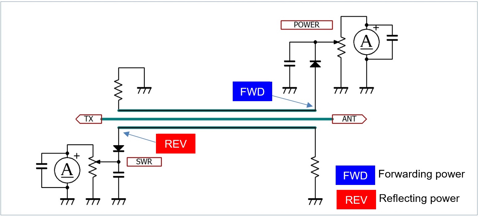
Figure 4. Internal circuit diagram drawn by looking at the real meter brought back from Nipponbashi
In actual operation, a chart as shown in Figure 5 was attached in the old days so that it was not necessary to calculate the SWR value with a formula from the traveling wave power and the reflected wave power each time. For example, if you send 50 W of power to the antenna and the reflected wave power of 2 W from the antenna at that time, you can read from this chart that SWR is 1.5.
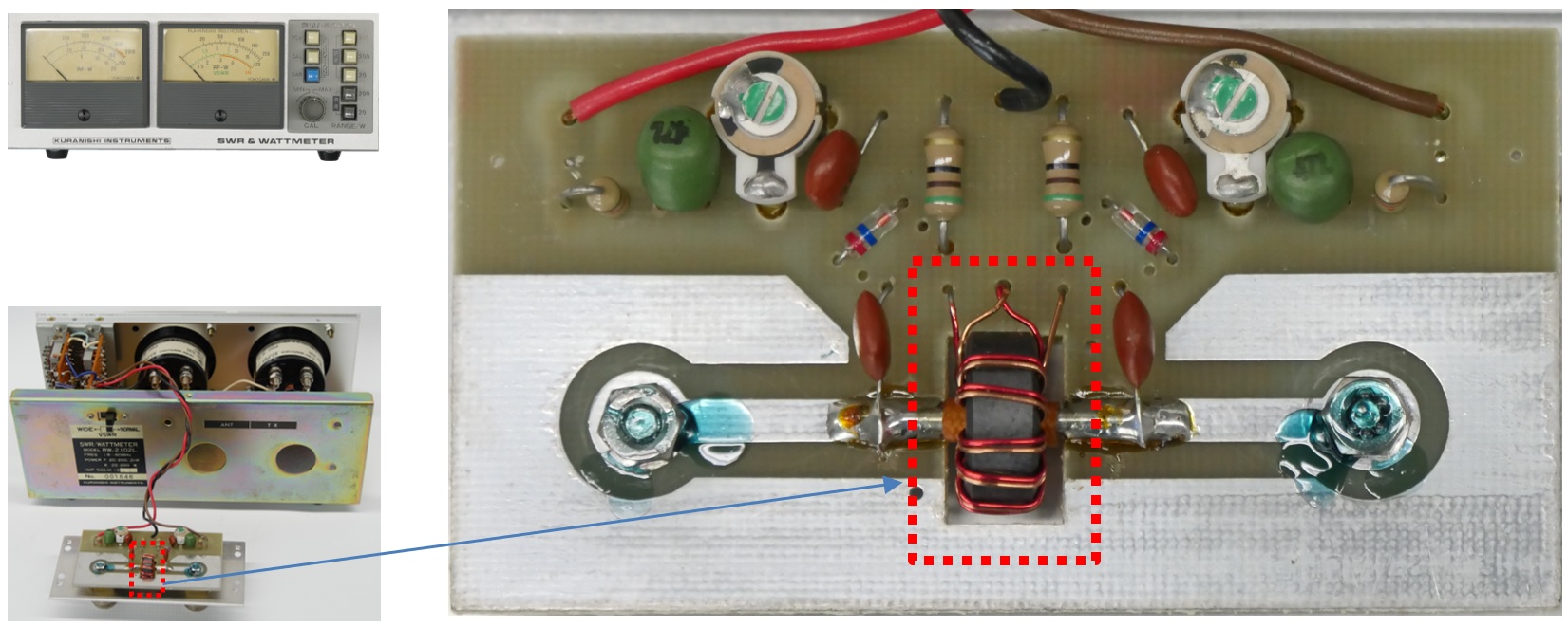
Figure 5. Chart for obtaining SWR values from forwarding and reflecting powers
(This chart is attached to BIRD 43 type power meter)
4. About CM coupling
C of CM coupling is “Capacitive coupling.” M stands for “Mutual Inductance.” In this CM-type power meter, we cannot see the specific capacitors and coils, such as which is C and which is M, but a CM-coupled circuit that is electrically composed of C and M is built in. These are the center conductor shown in the photo in Figure 3(a), and the pickup lines at both ends.
Figure 4 shows a schematic diagram of this meter inside. By terminating one end of the pickup line with a resistor, CM coupling works, and the power flowing through the pickup line has directionality. When RF power is sent from the transmitter to the antenna, the pickup line above the center conductor in Figure 3(a) induces power for forward waves. However, it does not induce power for reflected waves. On the other hand, the pickup line below the center conductor induces power for reflected waves, but does not induce power for forward waves. The CM-type power meter applies this principle.
Recently, due to the miniaturization and cost reduction of SWR meters, instead of a center conductor and pickup lines on both sides, a coil is wound around a toroidal core, and the coil detects the power of forward and reflected waves. Figure 6 below is an internal photo of a Kuranishi RW-2102L SWR/Power meter. The part of the coil surrounded by the dotted line is the CM coupling part.
5. Internal structure of another manufacturer's SWR meter
Figure 6 shows the inside of the Kuranishi RW-2102L SWR/POWER METER (currently the company no longer exists). There is no center conductor mentioned above and no pickup lines at both ends, but the center conductor is made of a print pattern on the PCB, and the detection of the forward wave and reflected wave is detected by the CM coil with a coil wound on a toroidal core. The circuit diagram of this meter is also shown in Figure 7 for reference.
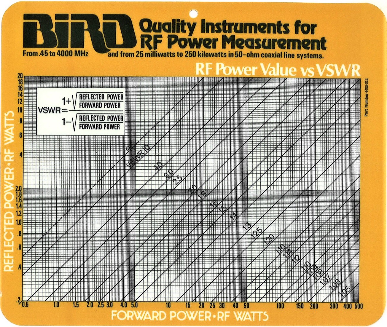
Figure 6. Internal structure of a Kuranishi SWR/POWER METER RW-2102L
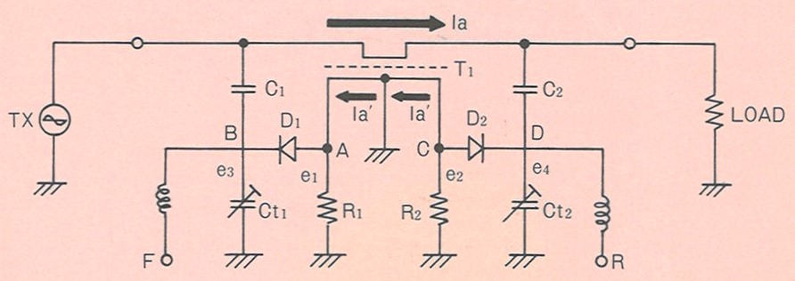
Figure 7. Circuit diagram of Kuranishi RW-2102L SWR/POWER METER
(Taken from the instruction manual)
FBDX
Technical Trivia by Dr. FB backnumber
- Generating “Sawtooth Waves” using a D/A conversion circuit and a counter IC
- Examining a D/A converter using a Resistor Ladder
- Electronic firefly and its circuit description
- Controlling the rotation speed of a DC motor
- Description of up-down counter using 74HC192 and 74HC4511 ICs
- Considerations when making a dual voltage power supply for operational amplifiers
- Observing filter characteristics with a white noise generator
- Is noise actually reduced in twisted pair cables?
- Experiments on divider circuits using a 74HC74
- Consideration of using a photocoupler as a voltage-variable resistor
- Distorted waveform spectrum as observed on a tinySA
- Trial making of a QFH antenna
- About the inductance of coils
- Operation of analog switches
- Small digital voltmeter, 2-wire type / 3-wire type. What is the difference?
- Constant current circuit using an Op-Amp
- Coaxial cable loss to UHF and SHF
- 2.4 GHz Wireless LAN Antenna
- Let’s use MOSFETS
- 25th Comparator
- The principle of PLL
- Examination of the MLA performance
- About the Fresnel zone of the SHF band
- Level difference under open and load ends of an SSG
- Is “Made in Japan” alive? (UHF adapter again)
- Possibility experiment of passive repeater with the Back-to-Back antenna
- Why you should make SWR measurements just below the antenna!
- How reliable is the L-type BNC?
- Is the Bird 43 accurate enough?
- Does a wire dipole antenna need a balun?
- Why we don’t use a silicon diode in a crystal radio?
- How to light the 7-segment LED
- Measurement of Antenna Performance on Handheld Transceivers (Part 3)
- Measurement of Antenna SWR on Handheld transceivers (Part 2)
- Measurement of Antenna SWR on Handheld transceivers(Part 1)
- An SWR meter
- V/UHF 3-Band Antenna Dismantling Note