


Technical Trivia by Dr. FB
Why you should make SWR measurements just below the antenna!

Dr. FB
I read an article about making an antenna that explained you should measure SWR just below the antenna. It also said, "Don't adjust the SWR with the length of the coaxial cable." However, shortening or lengthening the coaxial cable using an intermediate cable may improve the SWR value. If you have an acceptable SWR reading, do not finish the antenna adjustment because the SWR reading may not be right value. In this article, I will make an SWR measurement experiment focusing on the length of the coaxial cable.
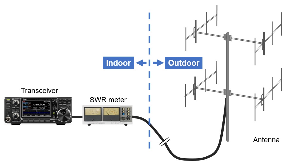
Figure 1. Typical SWR meter connections used by hams
What you need to know before measuring SWR
If you connect the SWR meter close to a radio that is several meters or tens of meters away from the antenna, as shown in Figure 1, and measure the SWR, the true SWR value of the antenna may not be obtained.
In that case, the antenna and transmission line are not matched, the same SWR value at the feed point of the antenna (just below the antenna) appears on the other end of the coaxial cable when the electrical length of the coaxial cable is an integral multiple of the λ/2 frequency. Similarly, if the electrical length of the coaxial cable is an odd multiple of λ/4 of the frequency, the SWR value measured just below the antenna and the SWR value measured on the radio do not match. This is because the feed point impedance of the antenna and the characteristic impedance of the coaxial cable do not match, causing a standing wave to occur in the coaxial cable. The length of the coaxial cable between the antenna and the radio makes the load impedance appear to change as seen from the transceiver side. Of course, this is not the case of an impedance of 50Ω, which is ideal for loads, as it does not generate standing waves.
Preparing the coaxial cable
Experiments are conducted using the 144MHz band, which has a reasonable wavelength and is easy to test. Since the SWR value seems to change depending on the length of the coaxial cable, I prepared the four different lengths of coaxial cables, shown in Figure 2.
When we make an antenna, we calculate the wavelength using the formula shown below. This is the calculation for obtaining the wavelength of 145MHz. When calculating the electrical length of a coaxial cable as one wavelength, multiply the length calculated by the formula below by 0.67 for 5D2V cable, for example. This 0.67 is called the "wavelength velocity factor “or just simply “velocity factor” of the coaxial cable. This occurs because the propagation speed of radio waves is slower when traveling through conductors such as coaxial cables than when traveling in free space. This velocity factor varies, depending on the type of coaxial cable, so check the specifications of the coaxial cable manufacturer before using it.
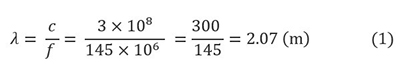
By conducting experiments at 145MHz, we will prepare coaxial cables at λ/4, 2λ/4(=λ/2), 3λ/4, and 1λ of that frequency. The length considering the wavelength shortening rate of the coaxial cable is called "electrical length.” The formula for calculating the electrical length 1λ (=one wavelength) of 5D2V cable at 145MHz is shown below.

Similarly, the table below shows the lengths of λ/4, λ/2, 3λ/4, and 1λ.
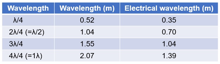
Figure 2. Wavelength and electrical length at 145MHz when using 5D2V cable (velocity factor= 67%)
Experiment 1: Connect a 50Ω load and the SWR meter next to the antenna.
The connection shown in Figure 3 is the ideal SWR measurement method described in any antenna building article. In other words, it is a method of measuring by connecting the SWR meter just below the antenna. In the experiment, the antenna used a pseudo load, a 50Ω dummy load. The coaxial cable is 5D2V made by FUJIKURA.
The experimental results were measured by changing the length of the coaxial cable, but in each case the SWR meter reading was 1:1.
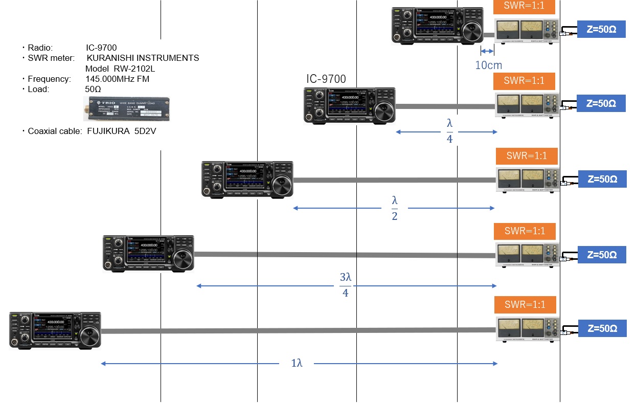
Figure 3. Use a 50Ω dummy load and connect the SWR meter next to the load
Experiment 2: Connect a 50Ω load and the SWR meter next to the radio.
Figure 4 is an experiment to see if the matched antenna changes the SWR reading with the length of the coaxial cable. In other words, the SWR meter assumes that it is located near the radio. The experimental result was SWR=1:1 regardless of the length of the coaxial cable in each case.
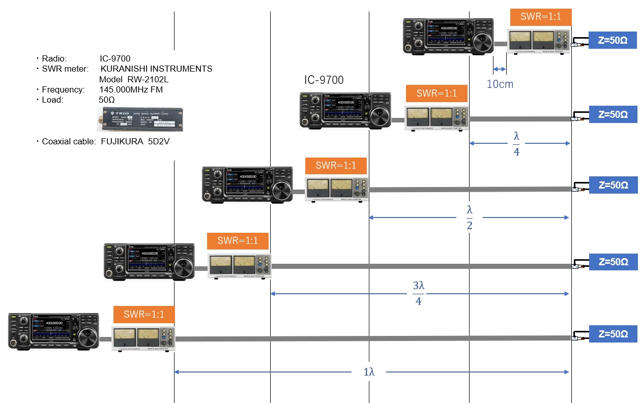
Figure 4. Use a 50Ω dummy load and connect the SWR meter next to the radio
Experiment 3: Connect a 120Ω load and the SWR meter next to the load.
Experiments 3 and 4 are cases where the condition is almost the same as the antenna and coaxial cable that we usually use. In other words, the SWR of the antenna is not perfectly 1:1 but 1.5:1 or 2:1.
I think that the case where SWR=3:1 is rare, but in this experiment, we made a pseudo condition of SWR 2:1 to 3:1 and conducted the experiment. The load is made by connecting eight 1.5 kΩ resistors in parallel. The resistance value was R=187Ω when measured with an Ohm meter, and Z (impedance)=120 Ω when it was measured with an impedance bridge.
Figure 5 is a connection diagram for the measurements. The measured values of SWR are also shown on it. The SWR meter is connected next to the load to measure the SWR. As expected, the SWR is generally between 2.5:1 and 3:1.
Originally, when SWR is measured next to the load it should be constant, regardless of the length of the coaxial cable between the SWR meter and the radio in theory. However, the actual measurement shows a difference of 0.5. This will be a verification task to be done at a later date.
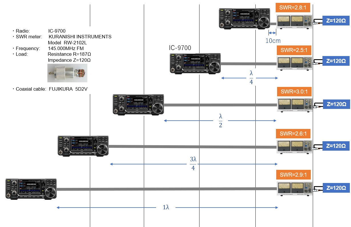
Figure 5. Using an unmatched load, connect the SWR meter next to the load
Experiment 4: Connect a Z=120Ω load and the SWR meter next to the radio.
This experiment 4 is the key point of this article. In other words, a homemade antenna is built to your house roof as it is, and RF power is supplied through a coaxial cable of an appropriate length to the antenna. The SWR meter is connected near the radio and measures the SWR there. This is a common case.
As seen in Experiment 3, a load with Z=120Ω is connected in advance, so the indicated value of the SWR meter may be 2:1 to 3:1. When the length of the coaxial cable is 10 cm, λ/2, and 1λ, the SWR values are 2.1:1, 2.8:1, and 2.5:1 respectively. In other words, it can be seen from this result that when a coaxial cable with a length that is an integral multiple of λ/2 is used, the state of the load end of the coaxial cable appears as it is on the opposite radio side.
On the contrary, when the SWR was measured with the coaxial cable having a length of λ/4 and 3λ/4, the SWR values are 1.4:1 and 1.5:1 respectively in this experiment. Although the actual SWR value is 3:1 in the experiment (3), the SWR meter shows approximately 1.5:1 for these lengths. When the antenna adjustment is completed as "OK! This is enough," the cable may have a standing wave, which results in the radio output not being radiated sufficiently from the antenna.
In this experiment 4, the SWR values of λ/4 and 3λ/4 are relatively similar, but the SWR values vary from 2.1:1, 2.8:1 and 2.5:1 when the cable lengths are integral multiples of λ/2. Originally, the SWR value measured just below the antenna should come out as approximately 3:1, but it seems that there is also something caused by the accuracy of the length of the manufactured coaxial cable.
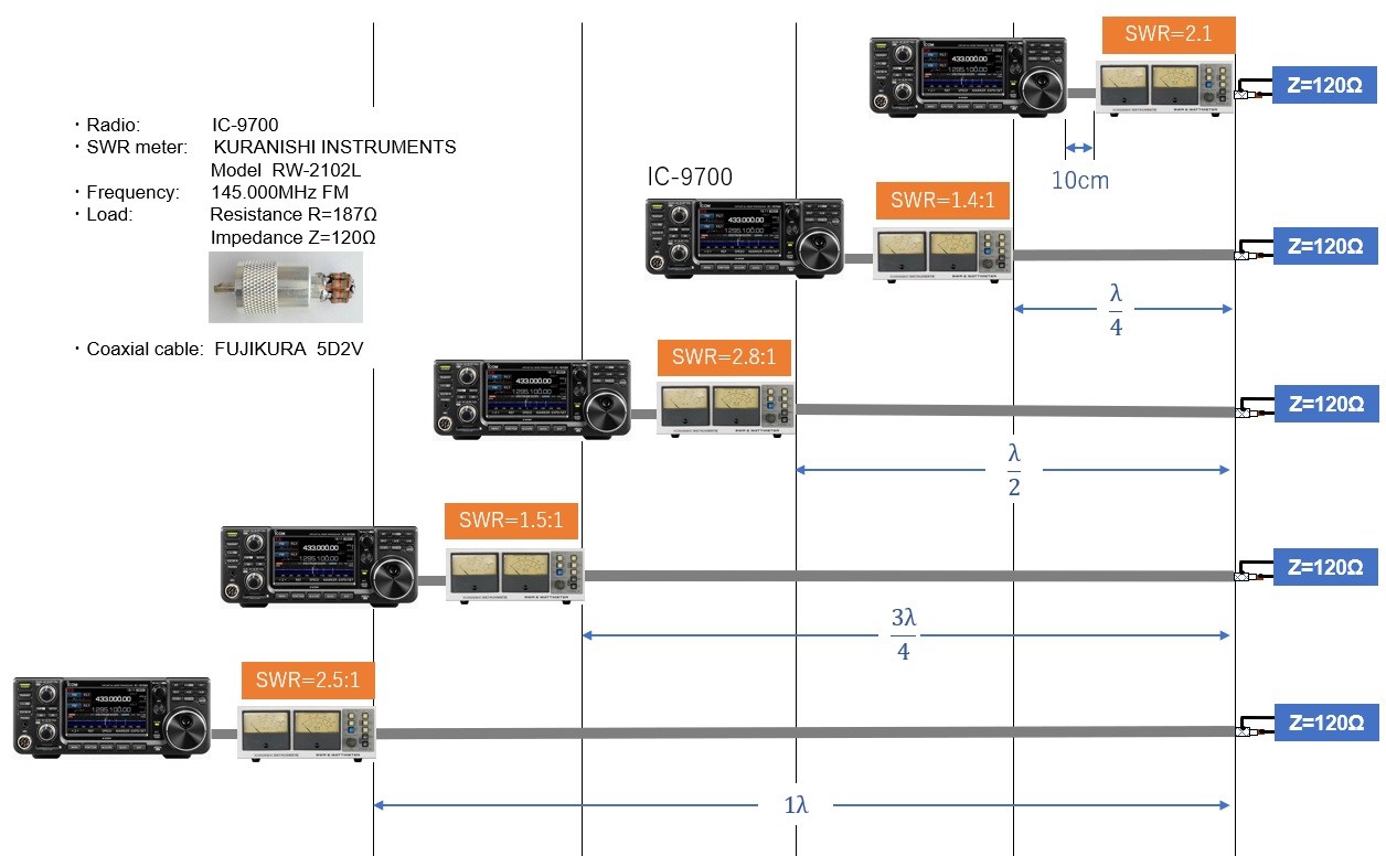
Figure 6. Using an unmatched load, connect the SWR meter near the radio
Summary
As mentioned above, experiment 4 is the key point of this article. In other words, when consciously connecting a load (Z=120Ω) of about SWR=3:1 and measuring SWR in experiment 3, the SWR meter shows close to 3, as expected. (Rightmost column in the table below)
However, in the key point experiment 4, there were times when SWR=3:1 was shown depending on the length of the coaxial cable, and there were times when it was lower than that. (Center column in the table below) In other words, placing the SWR meter inside the shack and measuring the SWR there means that the indicated value changes, depending on the length of the coaxial cable.
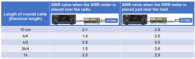
Figure 7. Summary of Experiment 3 and Experiment 4
When a multi-band antenna is connected to a single coaxial cable, it is not always possible to make the length of the coaxial cable an integral multiple of the electrical length λ/2 because wavelength varies, depending on operating bands.
As found in experiment 3, it is best to measure SWR just below the antenna. Even if the SWR meter is placed next to the radio, it shows an maximum SWR of 3:1. If the SWR is 1.5:1 under the antenna, when the antenna is installed, theoretically you do not have an emotional roller coaster of the meter reading.
However, in reality, if the SWR meter shows 3:1 when the SWR meter is placed next to the radio, the APC (Automatic Power Control) prevents the final transistors of the radio from being destroyed by antenna mismatching.
If this happens, the transmission output of the radio will decrease, and even if the antenna itself is matched, the power will be limited, which is a big problem for amateurs. We need to make the SWR value lower, but it is also necessary to fully consider the apparent SWR reduction on the radio side with an antenna tuner or antenna coupler.
FBDX
Technical Trivia by Dr. FB backnumber
- Generating “Sawtooth Waves” using a D/A conversion circuit and a counter IC
- Examining a D/A converter using a Resistor Ladder
- Electronic firefly and its circuit description
- Controlling the rotation speed of a DC motor
- Description of up-down counter using 74HC192 and 74HC4511 ICs
- Considerations when making a dual voltage power supply for operational amplifiers
- Observing filter characteristics with a white noise generator
- Is noise actually reduced in twisted pair cables?
- Experiments on divider circuits using a 74HC74
- Consideration of using a photocoupler as a voltage-variable resistor
- Distorted waveform spectrum as observed on a tinySA
- Trial making of a QFH antenna
- About the inductance of coils
- Operation of analog switches
- Small digital voltmeter, 2-wire type / 3-wire type. What is the difference?
- Constant current circuit using an Op-Amp
- Coaxial cable loss to UHF and SHF
- 2.4 GHz Wireless LAN Antenna
- Let’s use MOSFETS
- 25th Comparator
- The principle of PLL
- Examination of the MLA performance
- About the Fresnel zone of the SHF band
- Level difference under open and load ends of an SSG
- Is “Made in Japan” alive? (UHF adapter again)
- Possibility experiment of passive repeater with the Back-to-Back antenna
- Why you should make SWR measurements just below the antenna!
- How reliable is the L-type BNC?
- Is the Bird 43 accurate enough?
- Does a wire dipole antenna need a balun?
- Why we don’t use a silicon diode in a crystal radio?
- How to light the 7-segment LED
- Measurement of Antenna Performance on Handheld Transceivers (Part 3)
- Measurement of Antenna SWR on Handheld transceivers (Part 2)
- Measurement of Antenna SWR on Handheld transceivers(Part 1)
- An SWR meter
- V/UHF 3-Band Antenna Dismantling Note