


Radio Geek
Project No.2 Making an Up/Down counter (Part 2)

In the first article of "Radio Geek," a one-digit up-counter was made on a breadboard using two 74-series logic ICs and a few electronic components. The counter counts up when the tact switch that generates the clock signal is pushed, but chattering of the switch caused unexpected movement in the number of times the tact switch was pushed and the count on the 7-segment LED display. This time, I will take countermeasures to the unexpected movement of the LED and upgrade the number of digits to 2 digits.
About a Chattering phenomenon occurred
The circuit diagram of the one-digit up-counter introduced in the first article is shown again in Figure 1. The clock signal is produced by a circuit consisting of SW1 and R8.
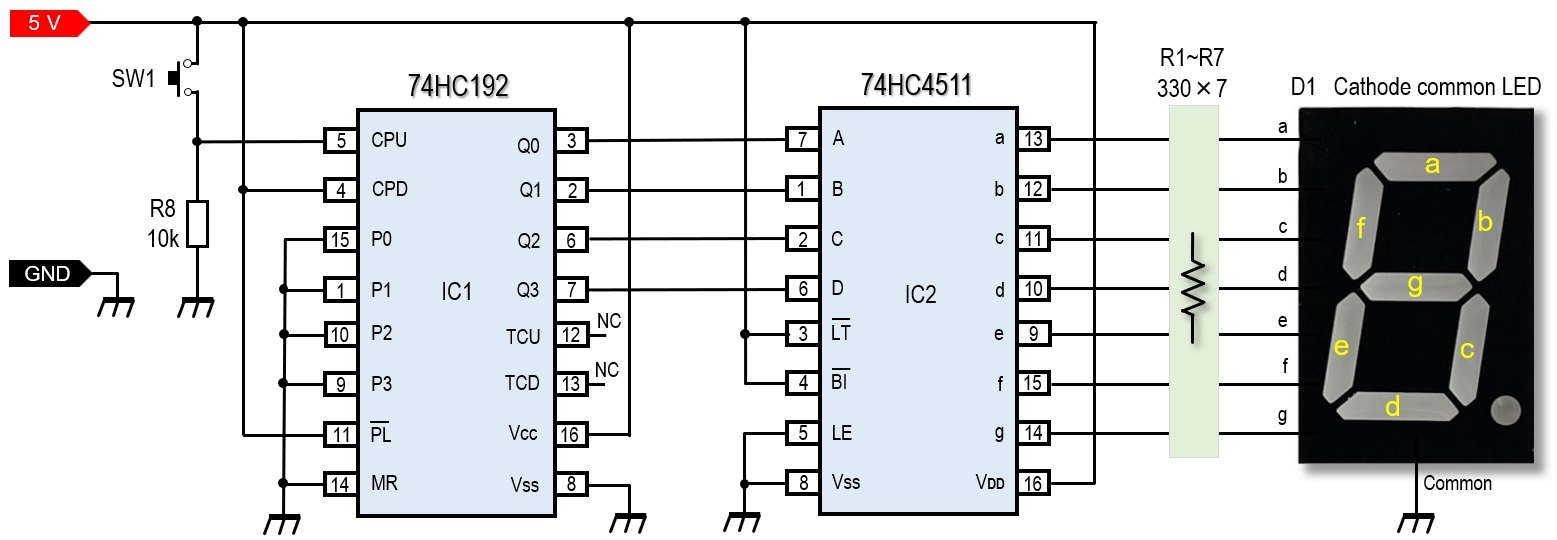
Figure 1. Schematic diagram of a 1-digit up-counter
When SW1 is open, the level of pin 5 is L because it is connected to GND through R8. To close SW1 changes pin 5 from L to H. At this time, although SW1 is only pushed once, there is actually a flutter between the contacts of the switch, and the contacts are repeatedly turned ON and OFF for a very short time, causing a state in which multiple clock signals are input to pin 5. This is called "chattering" of the switch.
Figure 2 shows an oscilloscope observation of this chattering phenomenon. In the left image, although SW1 is pushed only once, noise can be seen at the leading edge. This is the signal that is causing the counts to malfunction. The image on the right shows the waveform on the trailing edge when SW1 is released. Most of the time, the waveform is clean like this, but sometimes the waveform is mixed with noise and the counts are up, even when the switch is released.
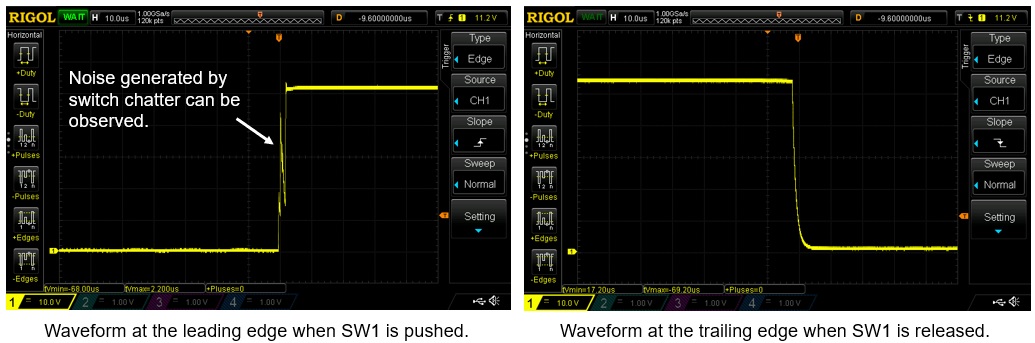
Figure 2. Observing the occurrence of chattering phenomenon with an oscilloscope
Schmitt Trigger Circuit
I have explained that an unwanted clock signal is generated even though SW1 is pushed only once. The circuit that removes this unnecessary clock signal is the anti-chattering circuit shown in Figure 3. It is called a Schmitt trigger circuit.
This Schmitt trigger circuit uses a 74HC14, 6-circuit Schmitt inverter (Hex Schmitt Inverter) in addition to CR components. 74LS type of logic ICs is also acceptable even if you do not have a 74HC type of logic IC. This IC is basically an inverter, but it has a function to generate a Schmitt trigger.
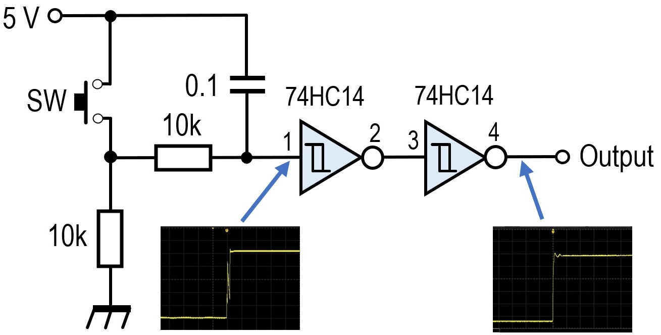
Figure 3. Anti-chattering circuit
A Schmitt trigger is a logic circuit with two different threshold levels on its inputs. The datasheet for the Toshiba TC74HC14AP shows that when the Vcc applied to this logic IC is 4.5 V, the maximum thresholds are 3.15 V and 2.0 V.
As you know, logic circuits work by operating with signals at H and L levels. Therefore, there is a threshold value that is recognized as "H" when the voltage is above a certain level and "L" when the voltage is below a certain level. The TC74HC14AP does not go H until the input level exceeds 3.15 V, but once it goes H, it does not go L until the input falls below 2.0 V. This is what is meant by the maximum 3.15 V and 2.0 V thresholds. The anti-chattering circuit uses this characteristic.
As you can see in the waveforms shown in Figure 3, a clock signal with noise mixed with chattering is input to the input of the Schmitt trigger circuit. However, the output is a clean clock signal at the leading edge.
Installing the Schmitt trigger circuit
Figure 4 shows a schematic diagram in which the Schmitt trigger circuit described earlier is written into a one-digit up-counter. When this Schmitt trigger circuit was built into the breadboard, SW1 was pushed, and the count-up condition was tested, no matter how many times or in what manner the switch was pushed, there was no miscounting. The effect of the Schmitt trigger circuit was outstanding.
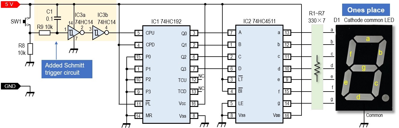
Figure 4. Adding a Schmitt trigger circuit to a one-digit up-counter
Upgrading to a 2-digit counter
Once a one-digit counter has been made, upgrading to a two-digit counter is not so difficult. Basically, you just need to make one more set of the one-digit counter shown in Figure 1. To further increase the number of digits to three, three sets of the same counter are required.
Figure 5 shows the schematic diagram of a 2-digit up-counter, where the red wires shown in the diagram are used to connect the first digit (ones place) counter to the second digit (tens place) counter. This red wire serves to transfer the carry-up signal to the counter at the tens place when the LED display at the ones place goes from 9 to 0. Operationally, the counter counts up every time one clock signal is input to pin 5 of IC1. When 9 clock signals are input, the level of pin 12 of IC1 changes from H to L, and when another clock signal is input, the level changes from L to H. In other words, when the LED display of the ones place digit goes from 9 to 0, pin 5 of IC4 reads this leading edge from L to H, and the count of the tens place digit is increased by one. This is repeated.
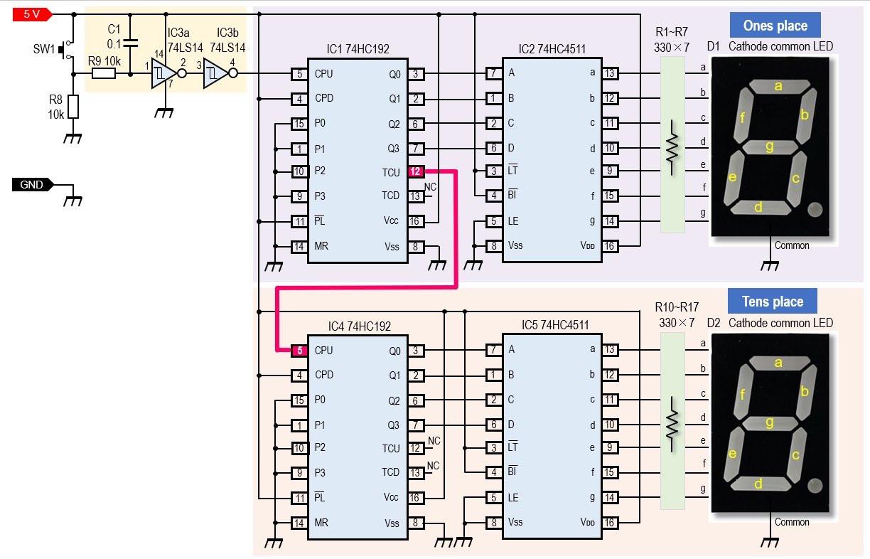
Figure 5. Schematic diagram of a 2-digit up-counter
Incorporating the ones place digit and tens place digit counters into a breadboard
Before installing the circuit shown in Figure 5 on a universal PCB, the tens place counter is also installed on the breadboard to check its operation. The breadboard can be wired repeatedly, so you can work without worrying too much about the layout. Since a Schmitt trigger circuit is also incorporated, switch chattering will be nonexistent.
Figure 6 shows two up-counters built into a breadboard, with green and red LEDs for the ones place digit and tens place digit displays respectively for test before installing the circuit to the universal PCB.
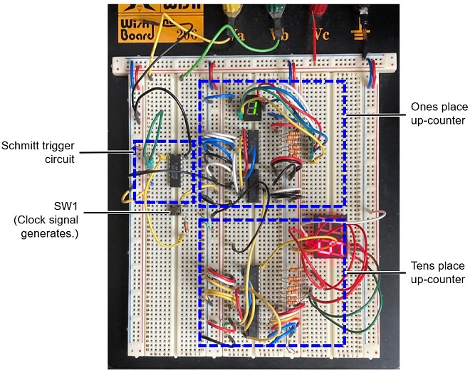
Figure 6. Preliminary operation check of a two-digit up-counter built into a breadboard
Summary
A one-digit up-counter using the 74HC192 and 74HC4511 in the Making an Up/Down counter (1) was built on a breadboard and its operation was verified. A one-digit up-counter was made, but chattering of the switch that generates the clock resulted in a movement that did not match the movement of the switch and the up-counter number.
In this up-counter described in the article (2), the above chattering has been upgraded by adding a Schmitt trigger circuit to counteract the chattering and by adding a digit to the tens place. Now the counter can count from 0 to 99 without malfunction by pushing the switch.
In the next article (3), I will upgrade the counter I have made this time.
CU
Radio Geek backnumber
- Making a 10-second IC Recorder for copying super-fast CW
- Making sequential turn signals
- Simple Electric Field Strength Meter with LED Display (Part 3)
- Simple Electric Field Strength Meter with LED Display (Part 2)
- Simple Electric Field Strength Meter with LED Display (Part 1)
- Again, building a simple inductance meter (Part 2)
- Again, building a simple inductance meter (Part 1)
- Building a simple inductance meter (Part 2)
- Building a simple inductance meter (Part 1)
- Project No.5 Upgrading the counter to 4-digits
- Project No.4 Making a push-up counter
- Project No.3 Making an Up/Down counter (Part 3)
- Project No.2 Making an Up/Down counter (Part 2)
- Project No.1 Making an Up/Down counter (Part 1)