


Radio Geek
Again, building a simple inductance meter (Part 2)

In Part 1, I briefly explained the principle of operation of an inductance meter, which measures the inductance of a coil. In this issue, I will continue with the experiment and building of the inductance meter. In order to simplify the building as much as possible, I will use own function generator for the RF oscillation circuit (Lo), which occupies half of the circuit. First, I will draw a circuit diagram, conduct experiments with a breadboard, and start building from the parts that worked well.
Completed the inductance meter
Circuit diagram
Figure 1 shows a block diagram of the simple inductance meter using the LC parallel resonance circuit shown in Part 1. Figure 2 is a circuit diagram of this block diagram, and unlike the RF signals produced with semiconductor and the LC resonance circuit (tuning circuit), the circuit diagram is much simpler because a function generator is used instead.
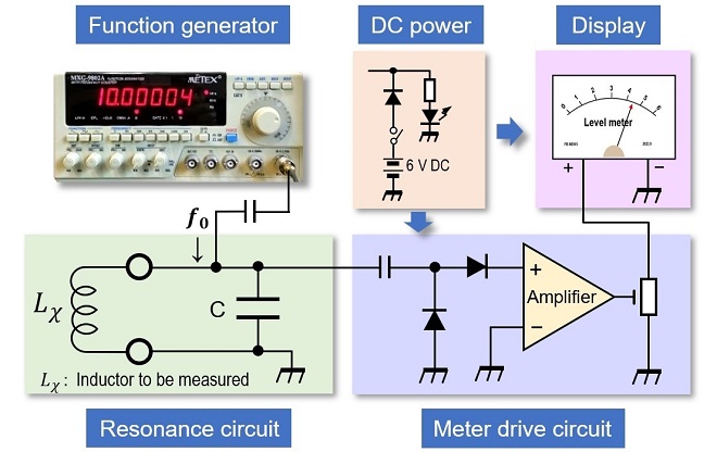
Figure 1. Block diagram of the simple inductance meter
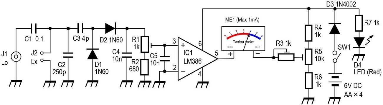
Figure 2. Block diagram schematic
Experiment
I experimented with the circuit shown in Figure 3 by taking out an RF signal input and the tuned circuit in the circuit diagram shown in Figure 2. For the experiment, I used a small variable capacitor for germanium radios in a plastic case for C2. The maximum capacitance of the variable capacitor is 260 pF, but I set the capacitance a little lower than the maximum, to around 250 pF. A 0.3 mH coil, which is known as Lx, was connected to terminal J2. The resonant frequency f0 in the parallel connection of 250 pF and 0.3 mH can be found to be 581 kHz from the formula shown below.

Connect an oscilloscope or a DC voltmeter capable of measuring very small voltages to the point shown in Figure 3. Set the frequency of the function generator to the calculated 581 kHz and slowly turn the C2 variable capacitor to maximize the value shown on the oscilloscope or voltmeter. At this point, the capacitance of the capacitor is 250 pF for Lx = 0.3 mH. Record the position of the capacitor's capacitance (250 pF) at this time. I used a small variable capacitor for C2 because I wanted to connect an accurate 250 pF. If a variable capacitor is not available, an ordinary capacitor can be used.
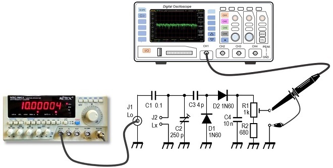
Figure 3. Experiments on tuned circuits
Building
The PCB shown in Figure 4 incorporates the circuit shown in Figure 2 on a 4 x 5 cm universal board. Figure 5 shows the completed inside in a resin case. The circuit uses 5 V, but since four 1.5 V dry-cell batteries produce 6 V, D3 is inserted in series to supply 5.3 V, subtracting 0.7 V for the difference in junction potentials of a diode. The insertion of D3 also functions as a reverse junction of the positive and negative sides of the dry cell battery. In the experiment, I used a 260 pF variable capacitor, but there is no particular need to use such a variable capacitor with a fixed capacitance.
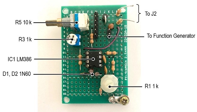
Figure 4. Universal circuit board with the circuit shown in Figure 2
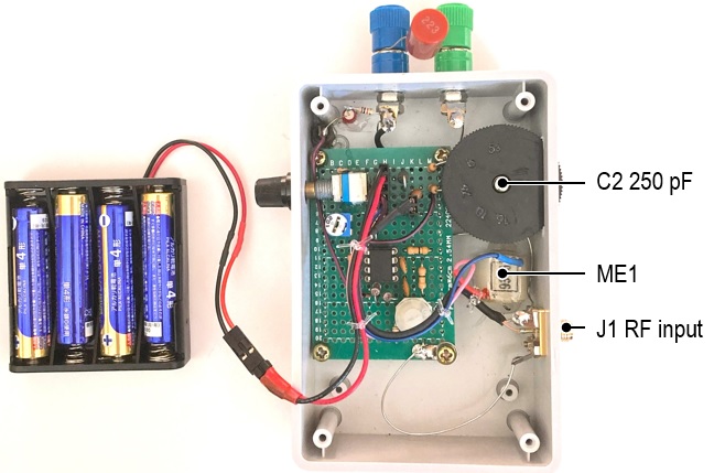
Figure 5. Inside the completed inductance meter
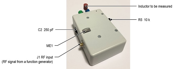
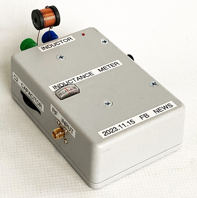
Figure 6. Completed inductance meter
Operation
This simple inductance meter does not directly display the value of inductance on the meter. Connect an inductor (coil) to be measured to the J2 terminal to form a parallel resonance circuit with a 250 pF capacitor. Since a 260 pF variable capacitor was used in the experiment, it was also used in this building. The RF signal (f) from the function generator is added to the circuit, and the inductance is calculated from the change in output voltage.
If the inductance (Lx) of the coil connected to J2 is not known at all, it is difficult to measure it, but if the approximate value is known, the value of Lx can be found from the table below by varying f.
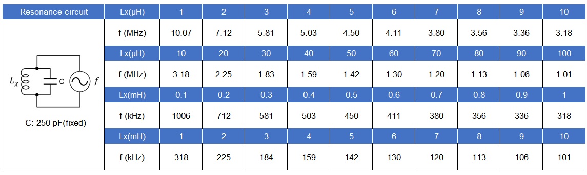
Figure 7. Resonance frequency chart
For example, to build a germanium radio, you need a variable capacitor and a coil. The capacitance of the variable capacitor is approximately 250 pF. If the meter oscillation is maximum around 581 kHz, the inductance of Lx is found to be 0.3 mH, which means that the AM radio can be covered from the lower limit to the upper limit by the variable capacitor.
If the inductance of the coil is milli-henry (mH) order, the peak of the meter is clearly visible, but if the inductance is on the order of microhenry (μH), it is difficult to tell unless you see the meter swing with your own eyes. However, when the voltage peaks are in the order of micro-henries (μH), it is difficult to determine the inductance unless you observe the meter's oscillation closely.
CU
Radio Geek backnumber
- Making a 10-second IC Recorder for copying super-fast CW
- Making sequential turn signals
- Simple Electric Field Strength Meter with LED Display (Part 3)
- Simple Electric Field Strength Meter with LED Display (Part 2)
- Simple Electric Field Strength Meter with LED Display (Part 1)
- Again, building a simple inductance meter (Part 2)
- Again, building a simple inductance meter (Part 1)
- Building a simple inductance meter (Part 2)
- Building a simple inductance meter (Part 1)
- Project No.5 Upgrading the counter to 4-digits
- Project No.4 Making a push-up counter
- Project No.3 Making an Up/Down counter (Part 3)
- Project No.2 Making an Up/Down counter (Part 2)
- Project No.1 Making an Up/Down counter (Part 1)