


Radio Geek
Project No.5 Upgrading the counter to 4-digits

Upgraded the counter from two to four-digit
I explained and built a two-digit counter from 0 to 99 in the first three articles in the counter series. I produced a push-up counter as an application of the two-digit counter in the fourth article. This time, I upgraded it to a four-digit counter.
Full schematic diagram of the four-digit counter
The full schematic diagram of a four-digit counter is shown in Figure 1. Just looking at the many logic ICs and the wiring of each IC is enough to demotivate you to build it. If you look closely, you will see that all the wires from the first to the fourth digit are the same, so it is not easy to make a four-digit counter all at once. But, if you have time, you can make one digit at a time and add one wire for each of the digits, as shown in pink in the schematic diagram.
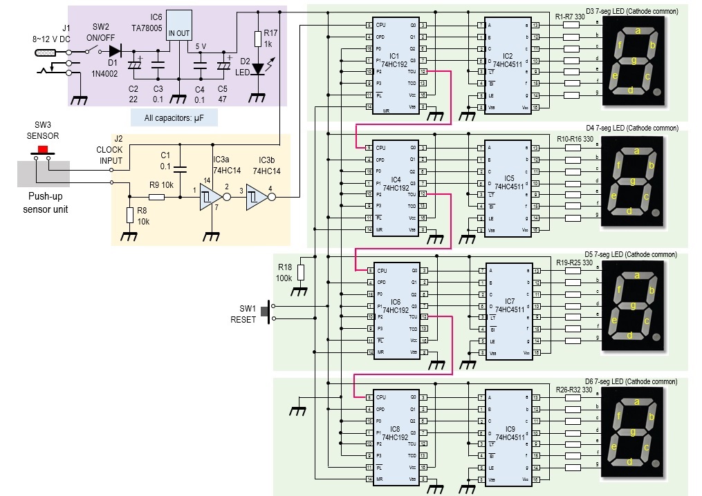
Figure 1. Full schematic diagram of a four-digit counter
Inside view of the counter
The inside of the counter is shown in Figure 2 below. Two 90 x 70 mm printed circuit boards (PCBs) are used for installing all components. Each PCB contains the circuit for two digits.
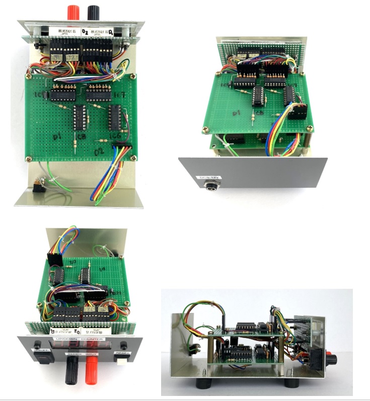
Figure 2. Inside view of the four-digit counter. Two PCBs are stacked.
Description of the complete counter
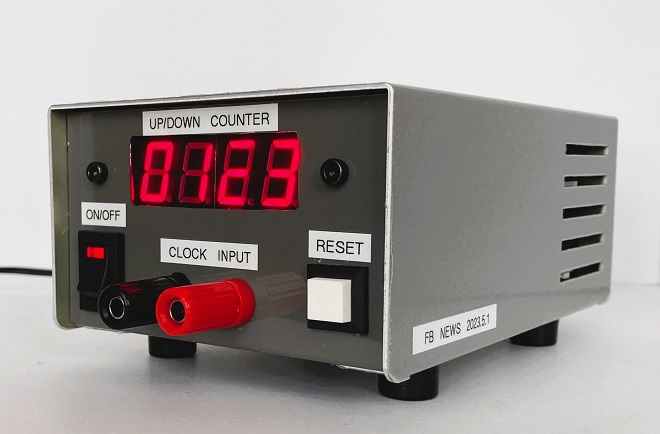
The size of the counter is 100 (W) x 150 (D) x 70 (H) mm.
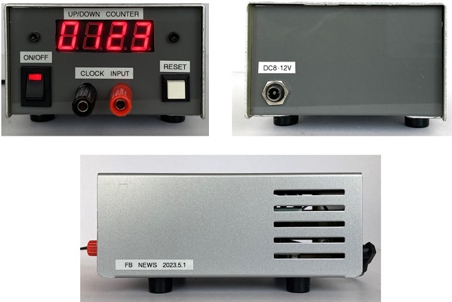
Figure 3. The completed four-digit counter
Considerations
Apply 8 to 12 V DC power to the counter after thoroughly checking the wiring. However, the maximum DC input voltage of the three-terminal regulator as shown IC6 in Figure 1 is 35 V, according to the Toshiba TA78005 specifications. If the input voltage is set too high, the value obtained by multiplying the difference between the input voltage and output voltage by the current will be consumed as heat. I applied 12 V because of a 12 V output AC adaptor on hand. The current consumption was measured to be 0.3 A, so the power consumption of this counter is P = 12 × 0.3 = 3.6 W.
As you can see from the picture of the front panel in Figure 3, the LEDs seem to be a little too bright. The current limiting resistor was set at 330 Ω for a voltage of 5 V applied to the LEDs, but if this is increased to 560 Ω, the LEDs used in this project will be of moderate brightness. By changing the current limiting resistor from 330 Ω to 560 Ω, the current per segment is reduced from approximately 13 mA to 7.6 mA, which also reduces power consumption. The brightness of the LED depends on the specifications of the 7-segment LED used, so it is safer to test the current limiting current in the initial design before moving on to production.
CU
Radio Geek backnumber
- Making a 10-second IC Recorder for copying super-fast CW
- Making sequential turn signals
- Simple Electric Field Strength Meter with LED Display (Part 3)
- Simple Electric Field Strength Meter with LED Display (Part 2)
- Simple Electric Field Strength Meter with LED Display (Part 1)
- Again, building a simple inductance meter (Part 2)
- Again, building a simple inductance meter (Part 1)
- Building a simple inductance meter (Part 2)
- Building a simple inductance meter (Part 1)
- Project No.5 Upgrading the counter to 4-digits
- Project No.4 Making a push-up counter
- Project No.3 Making an Up/Down counter (Part 3)
- Project No.2 Making an Up/Down counter (Part 2)
- Project No.1 Making an Up/Down counter (Part 1)