


Radio Geek
Project No.3 Making an Up/Down counter (Part 3)

In the part 1 of Radio Geek, a one-digit up counter was built on a breadboard using two 74-series logic ICs and a few electronic components, and its operation was checked. In the part 2, I upgraded the digits to be displayed to two, and made it possible to count from 0 to 99. In addition, as the counter sometimes produced errors, a circuit was added to solve the problem. In this part 3, I will carry out the actual production with future upgrades in mind.

Specifications of the up counter to be built
The basic counter is a two-digit up counter, but with a view to upgrading it, the following specifications will be used.
- Firstly, a two-digit up counter, with the circuit built into a universal PCB.
- the layout is designed with a four-digit up counter in mind.
- the counter and the sensor connected to it should be separate units.
- The counter is installed with a 'Reset' button to reset the count.
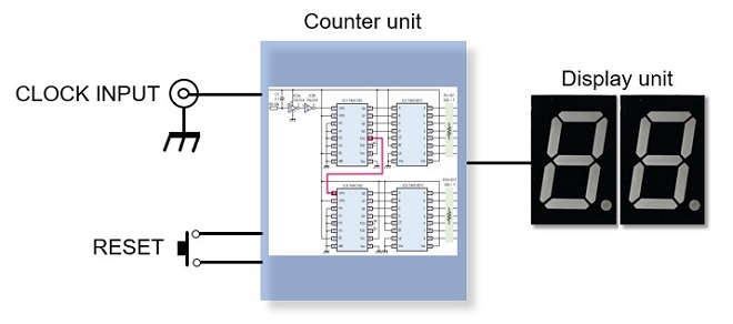
Figure 1. Concept diagram of the up down counter to be built.
Schematic diagram of the two-digit up counter
The project is divided into a counter unit and a display unit, as shown in Figure 1. Figure 2 shows the complete schematic diagram of the counter to be made. The power supply for the circuit was considered to be a dry cell battery, but when all seven segments are lit up, a current of about 100 mA flows for one digit, and 400 mA for four digits. That means that the battery will run down significantly, so I decided to use an AC adaptor this time.
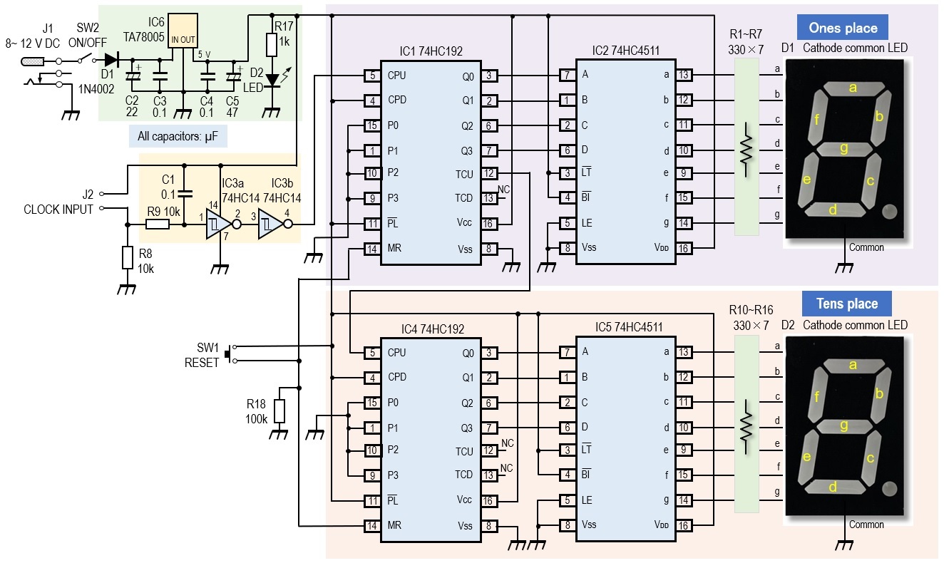
Figure 2. Full circuit diagram of the 2-digit up counter.
Integration into universal PCBs diagram of the two-digit up counter
It was explained in Making an Up/Down counter (Part 1) that two logic ICs are required to make up a one-digit counter. In this up counter, four logic ICs are mounted on a 90 mm x 70 mm universal PCB, aiming first at a two-digit counter from 00 to 99.
An aluminum case measuring W100 mm x D150 mm x H60 mm was used to incorporate the universal PCB. For the display, a cathode common LED with two digits in one is used. Seven-segment LEDs are available in dynamic lighting types, which are controlled by microprocessor signals, and static types, in which each segment is lit individually, as in this case. Note that they look very similar. I used LN526ALKs in this project, but any cathode common static type LED will light up.
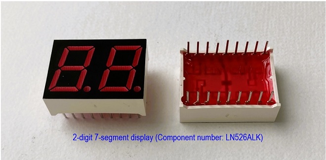
Figure 3. 7-segment LED with one 2-digit display (Static type LED).
Drilling holes in the aluminum case
The following holes are drilled in the aluminum case.
- Window frame for 7-segment LED (for 4-digit display for future upgrades)
- PCB mounting screw holes
- Jack for external DC power supply
- RESET button
- Clock signal input terminals for counting
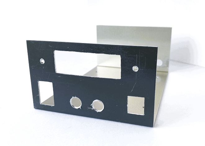
Figure 4. Completed drilling of aluminum case.
Making the counter unit and display unit
The counter unit consists of two 74HC192 and two 74HC4511 ICs mounted on a single universal PCB, as described above, to form a two-digit counter. The display unit is a seven-segment LED, so a total of eight wires are connected between the display unit and the counter unit, one for each segment plus the common terminal for each digit.
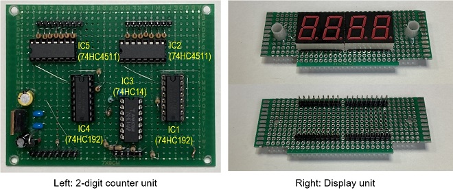
Figure 5. Completed PCBs with logic ICs and LEDs mounted on each universal PCB.
Making the wiring harnesses
The wiring of each unit can be done by direct connection of the leads, but for future upgrades and maintenance in case of breakdowns, each unit should be wired via a connector so that it can be removed easier. Figure 6 shows reference pictures of a wiring harness with wire housings.

Figure 6. Wiring harnesses connecting the various units.
Installation of each unit and terminals
In addition to the counter unit and display unit, install the input/output terminal components to complete the assembly.
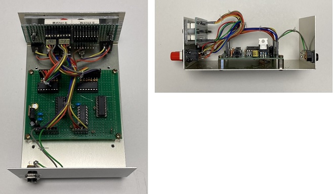
Figure 7. Finished counter with each unit and input/output terminals installed
Checking the operation
When the power switch is switched ON, the two-digit counter displays "00." Connect an ON/OFF momentary switch to the clock input terminal. Since this is an experiment, any switch can be used, but a non-locking momentary switch is appropriate.
First, quickly and repeatedly turn the switch connected to the clock signal input terminal ON and OFF. If the display shows an increase in the number according to the switch ON/OFF, the unit is operating normally. Next, push that switch and set the counter figure to "99." Then push the switch one more time to carry the digit forward and set the display to “00.”
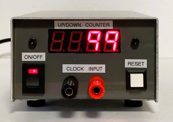
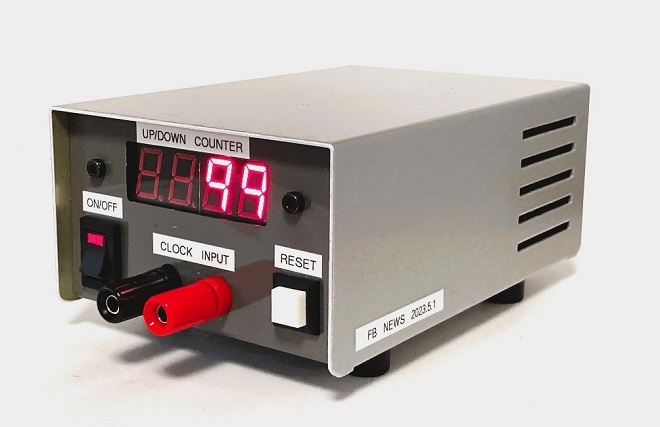
Figure 8. Front panel of the completed up counter. Pushing the REST button sets it to 00.
Next, stop the counter at the appropriate point and push the RESET button, making sure that the display shows “00.” Resetting the display is carried out by setting the MR (Master Reset) pin on pin 14 of the 74HC192 to H. The MR pin is normally at the L level and is set to H when a reset is applied. The MR pin should be pulled down with R19 (100 kΩ) to ensure that the MR pin is at a low level when a reset is not applied.
Actual operation
If the above checks are normal, the unit can be used as a 2-digit up counter. However, as only the counter part was made this time, there is no sensor part to count anything. First, as mentioned earlier, attach a momentary switch to the clock input terminal and enjoy the up counter.
Future development
The basic two-digit up counter is now complete. Depending on what you want to count, two digits may not be enough, so I will upgrade the counter to at least four digits.
CU
Radio Geek backnumber
- Making a 10-second IC Recorder for copying super-fast CW
- Making sequential turn signals
- Simple Electric Field Strength Meter with LED Display (Part 3)
- Simple Electric Field Strength Meter with LED Display (Part 2)
- Simple Electric Field Strength Meter with LED Display (Part 1)
- Again, building a simple inductance meter (Part 2)
- Again, building a simple inductance meter (Part 1)
- Building a simple inductance meter (Part 2)
- Building a simple inductance meter (Part 1)
- Project No.5 Upgrading the counter to 4-digits
- Project No.4 Making a push-up counter
- Project No.3 Making an Up/Down counter (Part 3)
- Project No.2 Making an Up/Down counter (Part 2)
- Project No.1 Making an Up/Down counter (Part 1)